
Formation of glass bumps with increased height using thermal annealing

a technology of thermal annealing and bumps, which is applied in glass tempering apparatus, manufacturing tools, instruments, etc., can solve the problems of increasing the insulating properties of the window while maintaining cost, and not being able to achieve greater bump heights relative to other problems, to achieve the effect of reducing or relieving laser-induced stress in the glass substrate and increasing the bump heigh

Inactive Publication Date: 2011-05-05
CORNING INC
View PDF11 Cites 22 Cited by
  • Summary
  • Abstract
  • Description
  • Claims
  • Application Information

AI Technical Summary

Benefits of technology

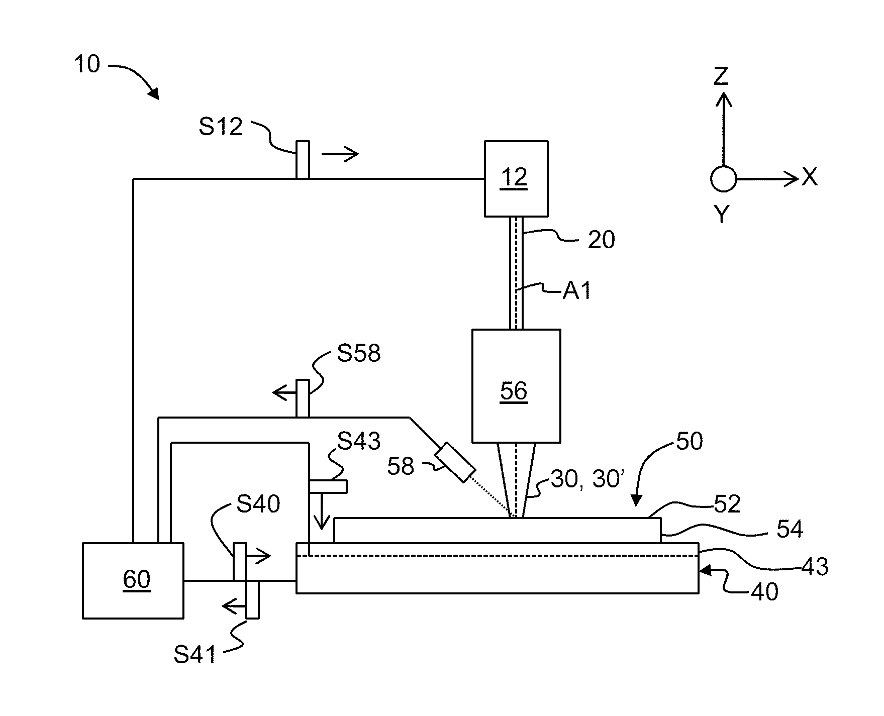
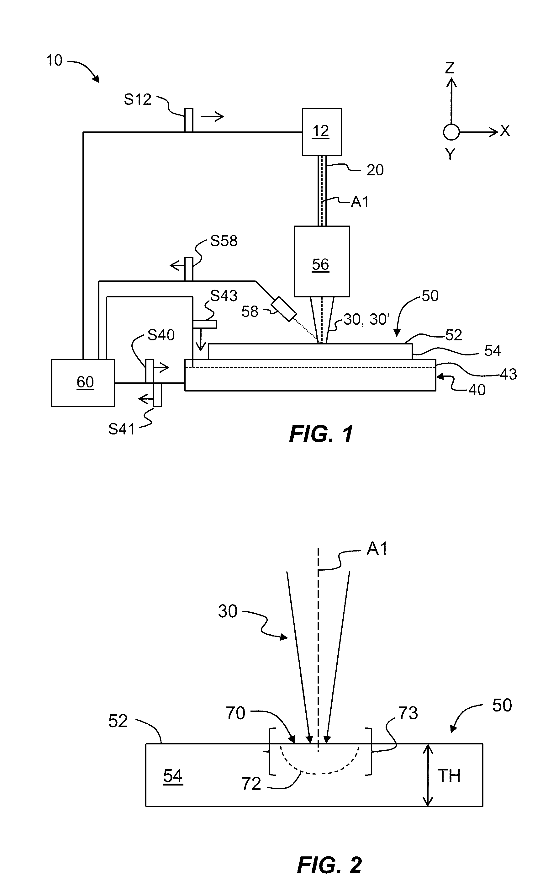
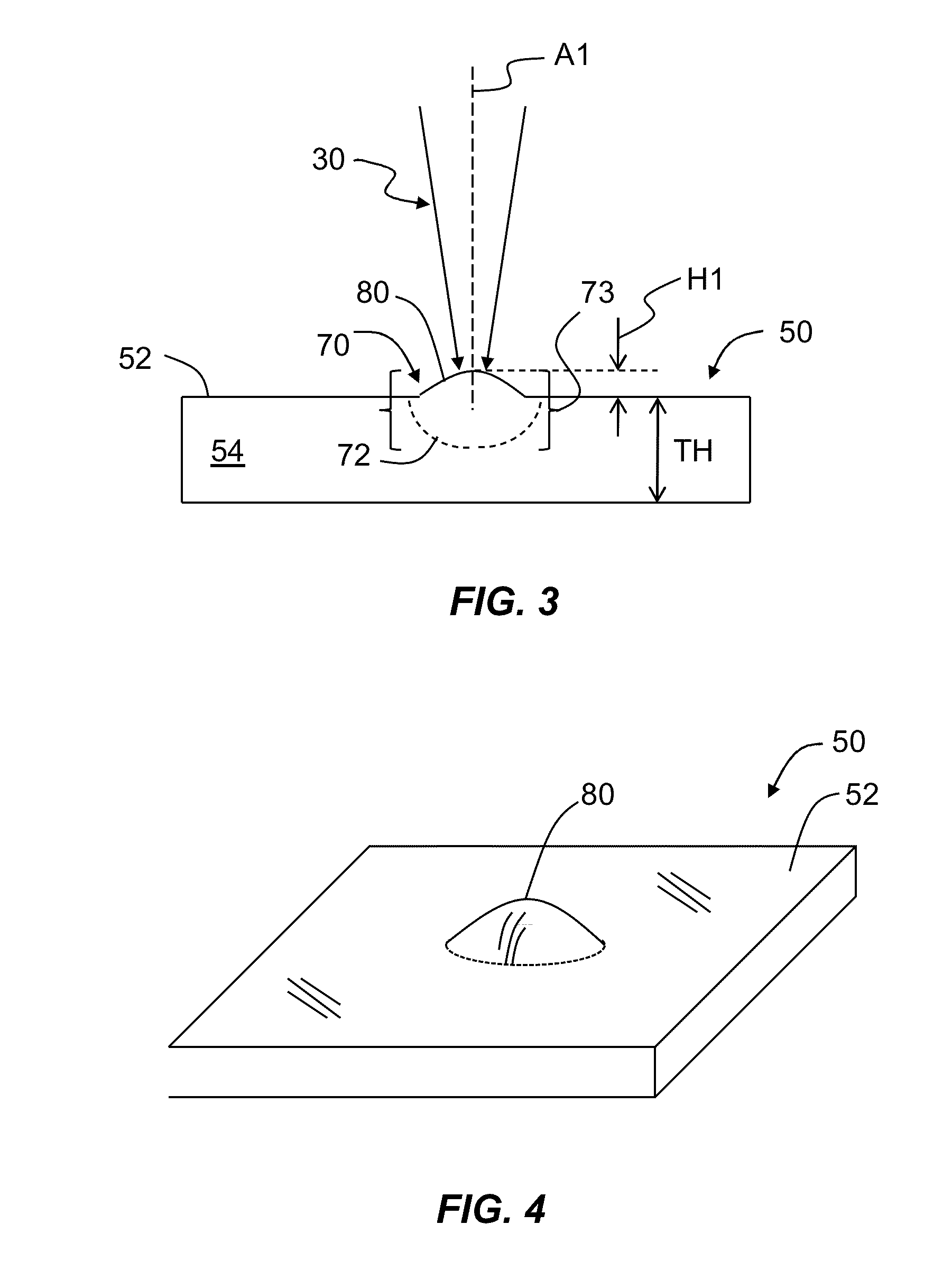
[0006]An aspect of the disclosure is a method of forming at least one bump on a surface of a glass substrate. The method includes performing a local irradiation of the glass substrate to form the at least one bump having an initial height. The method also includes thermally annealing at least a portion of the glass substrate to a temperature and for a duration that reduces or relieves laser-induced stress in the glass substrate. The method further includes increasing the bump height by irradiating the bump.
[0007]Another aspect of the disclosure is a method of forming a bump in a glass substrate having a surface and a body portion. The method includes performing a first irradiation of a portion of the glass substrate to form the bump in the glass surface, with the bump having a first height. The method also includes performing a first thermal annealing of the first irradiated portion. The method also includes performing a second irradiation of at least part of the first irradiated portion to increase the height of the bump to a second height greater than the first height.
[0008]Another aspect of the disclosure is method of forming at least one bump on a surface of a glass substrate. The method includes irradiating a first portion of the glass substrate with a first laser beam to form at least one bump having a first height H1. The method also includes thermally annealing at least a portion of the glass substrate to reduce or relieve glass stress formed during the irradiating. The method also includes irradiating the at least one bump with a second laser beam to increase the bump height to a second height H2>H1.

Problems solved by technology

Thus, for a given glass selection, greater bump heights have not been achievable relative to the substrate thickness because of the glass saturation effect.
Increasing the size of the space without increasing the pane thickness would increase the insulating properties of the window while maintaining cost.

Method used


Image

  • Formation of glass bumps with increased height using thermal annealing
  • Formation of glass bumps with increased height using thermal annealing
  • Formation of glass bumps with increased height using thermal annealing

Examples


Embodiment Construction

[0023]Reference is now be made in detail to the present preferred embodiments of the disclosure, examples of which are illustrated in the accompanying drawings. Whenever possible, the same reference numerals or symbols are used throughout the drawings to refer to the same or like parts.

[0024]In the discussion below, the “bump” is broadly understood to include any raised feature on the surface of a glass substrate caused by local heating and swelling of the substrate, including isolated bumps, groups or arrays of bumps having the same or different heights, one or more ridges, including ridges of varying heights and configurations (e.g., lines, concentric circles, squares and other shapes, etc.), and generally all variety of more complex surface features resulting from combinations of bumps, ridges, mesas, gratings and like raised features.

[0025]Also, the term “glass substrate” is intended to mean any type of glass material in any form, such as a glass plate, a glass block, a piece of...


PUM

PropertyMeasurementUnit
Fractionaaaaaaaaaa
Fractionaaaaaaaaaa
Fractionaaaaaaaaaa

Abstract

The disclosure teaches methods of forming at least one bump in a glass substrate having a surface and a body portion. The method includes performing a first irradiation of a portion of the glass substrate to form in the glass surface the at least one bump having bump height. The method also includes performing thermal annealing of at least a portion of the glass substrate that includes the first irradiated portion. The method then includes performing a second irradiation of the bump to increase the bump height.

Description

FIELD[0001]This disclosure relates to the formation of bumps on glass using laser irradiation, and in particular relates to methods for forming such bumps having increased height through the use of thermal annealing.BACKGROUND[0002]The effect of glass swelling when glass is locally irradiated with a laser is known. Bumps, 100 micrometers or taller, can be formed by heating a glass surface with an infrared laser beam having sufficient energy. References that describe the formation of bumps on glass using laser irradiation include U.S. Pat. Nos. 7,480,432 and 7,505,650, which patents are incorporated by reference herein, and the article by Grzybowski et al., entitled “Extraordinary laser-induced swelling of oxide glasses,” Opt. Express 17, 5058-5068 (2009), which article is incorporated by reference herein.[0003]When fabricating bumps with a laser beam incident upon on a glass surface, there is the maximum achievable height based on the glass composition and the laser-irradiation cond...

Claims


Application Information

Patent Timeline
IPC IPC(8): C03B25/00
CPCC03B23/006G02B6/02147C03B23/02E06B3/66304C03B2215/414C03C23/0025
Inventor DICKINSON, JR., JAMES EDWARDGRZYBOWSKI, RICHARD ROBERTHARVEY, DANIEL R.LOGUNOV, STEPHAN LVOVICHSTRELTSOV, ALEXANDER MIKHAILOVICH
Owner CORNING INC
Learn More