Systems and methods for optimizing power loads in a power distribution unit

a power distribution unit and power load technology, applied in the field of power distribution system and method, can solve the problem that none of these rack power distribution units provides feedback to the operator

Active Publication Date: 2011-05-05
AMERICA POWER CONVERSION CORP
View PDF23 Cites 55 Cited by
  • Summary
  • Abstract
  • Description
  • Claims
  • Application Information

AI Technical Summary

Benefits of technology

[0012]Embodiments of the power strip may further comprise a display to display the preferential order of outlets and / or a communication network to send the preferential order of outlets over. The processor may be further configured to obtain real-time current measurements of each phase of the single or three phase power input of the power strip, obtain real-time current measurements of each of the plurality of circuit breakers of the power strip, and log the real-time current measurements of each phase of the single or three phase power input and the circuit breakers. The processor, when analyzing the real-time current measurements of each phase of the single or three phase power input and the circuit breakers, identifies a user preference between preventing an overload of one of the plurality of circuit breakers and balancing phase load of the single or three phase power input when employing three phase power input. The power strip may further comprise a sensor to identify whether a particular outlet of the plurality of outlets is occupied.

Problems solved by technology

However, none of these rack power distribution units provide feedback to the operator incorporating the historical current measurements of the single or three phase input and the circuit breakers to improve the management and efficiency of the rack power distribution units in applying new loads to the power distribution unit.

Method used


Image

  • Systems and methods for optimizing power loads in a power distribution unit
  • Systems and methods for optimizing power loads in a power distribution unit
  • Systems and methods for optimizing power loads in a power distribution unit

Examples


Embodiment Construction

[0019]For the purposes of illustration only, and not to limit the generality, the present disclosure will now be described in detail with reference to the accompanying figures. This disclosure is not limited in its application to the details of construction and the arrangement of components set forth in the following description or illustrated in the drawings. The disclosure is capable of other embodiments and of being practiced or being carried out in various ways. Also the phraseology and terminology used herein is for the purpose of description and should not be regarded as limiting. The use of “including,”“comprising,”“having,”“containing,”“involving,” and variations thereof herein, is meant to encompass the items listed thereafter and equivalents thereof as well as additional items.

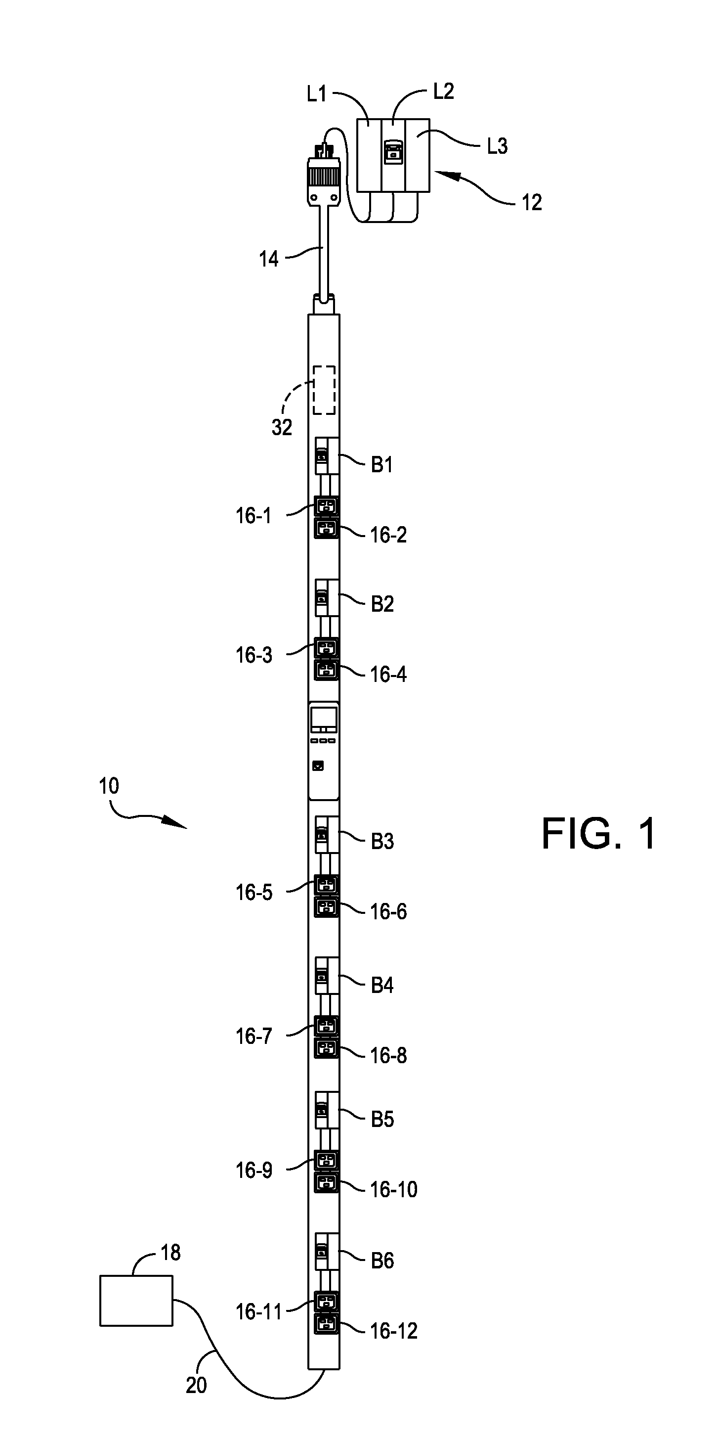
[0020]In accordance with several embodiments of the present disclosure, a power distribution unit is set forth that may provide electrical power and power management to one or more computer systems a...


PUM


Abstract

A method of optimizing power loads of a power strip is disclosed. The power strip is of the type having single or three phase power input, a plurality of circuit breakers, and a plurality of outlets. The arrangement is such that at least one circuit breaker is associated with at least one outlet. The method includes: obtaining real-time current measurements for each phase of the single or three phase power input of the power strip; obtaining real-time current measurements for each circuit breaker of the plurality of circuit breakers of the power strip; logging the real-time current measurements for each phase of the single or three phase power input and for each circuit breaker of the plurality of circuit breakers; and analyzing the real-time current measurements of the single or three phase power input and the plurality of circuit breakers to determine a preferential order of outlets in which to apply a new load.

Description

BACKGROUND OF THE DISCLOSURE[0001]1. Field of the Disclosure[0002]The present disclosure generally relates to improvements to a power distribution system and method, and more particularly to advanced power calculations and user interfaces to improve reliability and energy efficiency of a power distribution system, such as an intelligent power strip, and user or operator interaction with such a system.[0003]2. Discussion of Related Art[0004]Intelligent rack-mounted power distribution units, sometimes referred to as “rack PDUs,” may include at least one branch input power feed, single or three phase, with multiple receptacles to power attached equipment. Rack PDUs often include metering functions to measure and calculate voltage, current, power, and environmental data as well as a processor, memory and network management device for remote communication and management. Historically, rack PDUs measure aggregate load data based on phases and / or breaker banks, most often feeding multiple ...

Claims


Application Information

Patent Timeline
Patent Type & Authority Applications(United States)
IPC IPC(8): H02J3/00G01R21/06G06F19/00
CPCH02J3/14H02J1/14H02J2310/60
Inventor JANSMA, MICHAEL
Owner AMERICA POWER CONVERSION CORP
Why Eureka
Try Eureka