
Intra-subframe time multiplexing

a time multiplexing and subframe technology, applied in the field of single-frequency network frame generation and handling, can solve the problem of limited possibility of specifying some subframes as “mbsfn”

Inactive Publication Date: 2011-05-05
TELEFON AB LM ERICSSON (PUBL)
View PDF7 Cites 60 Cited by
  • Summary
  • Abstract
  • Description
  • Claims
  • Application Information

AI Technical Summary

Benefits of technology

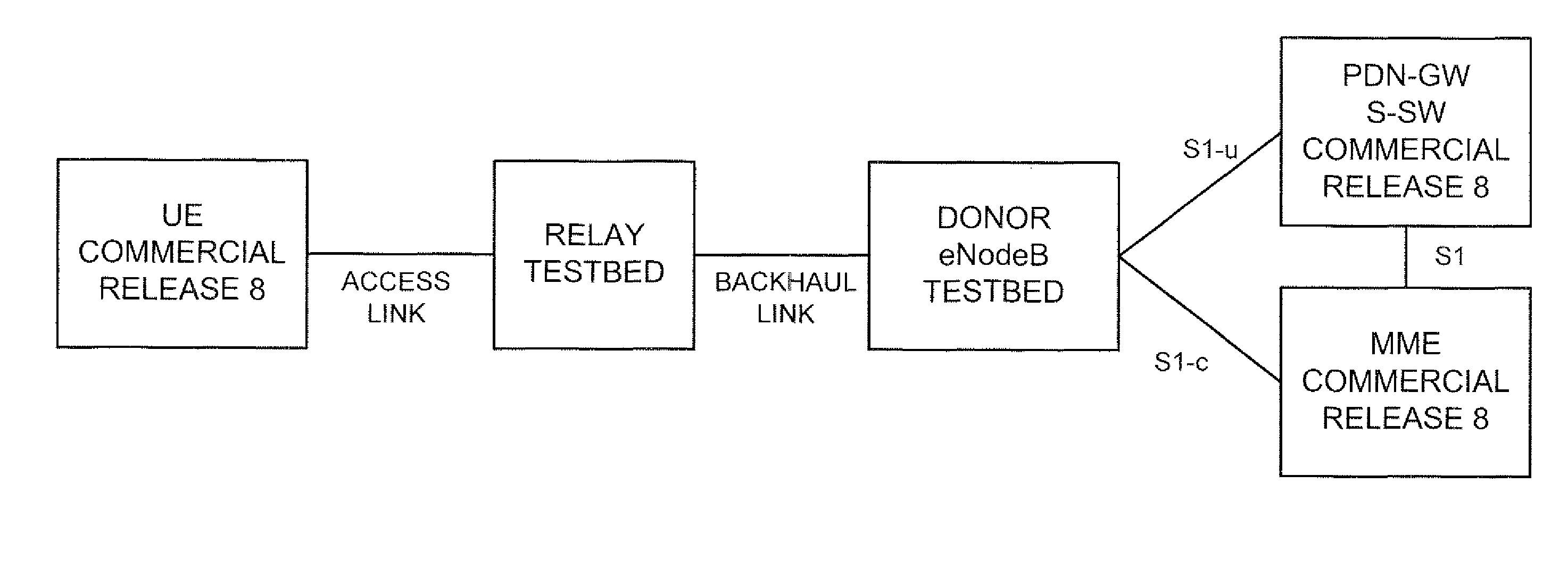
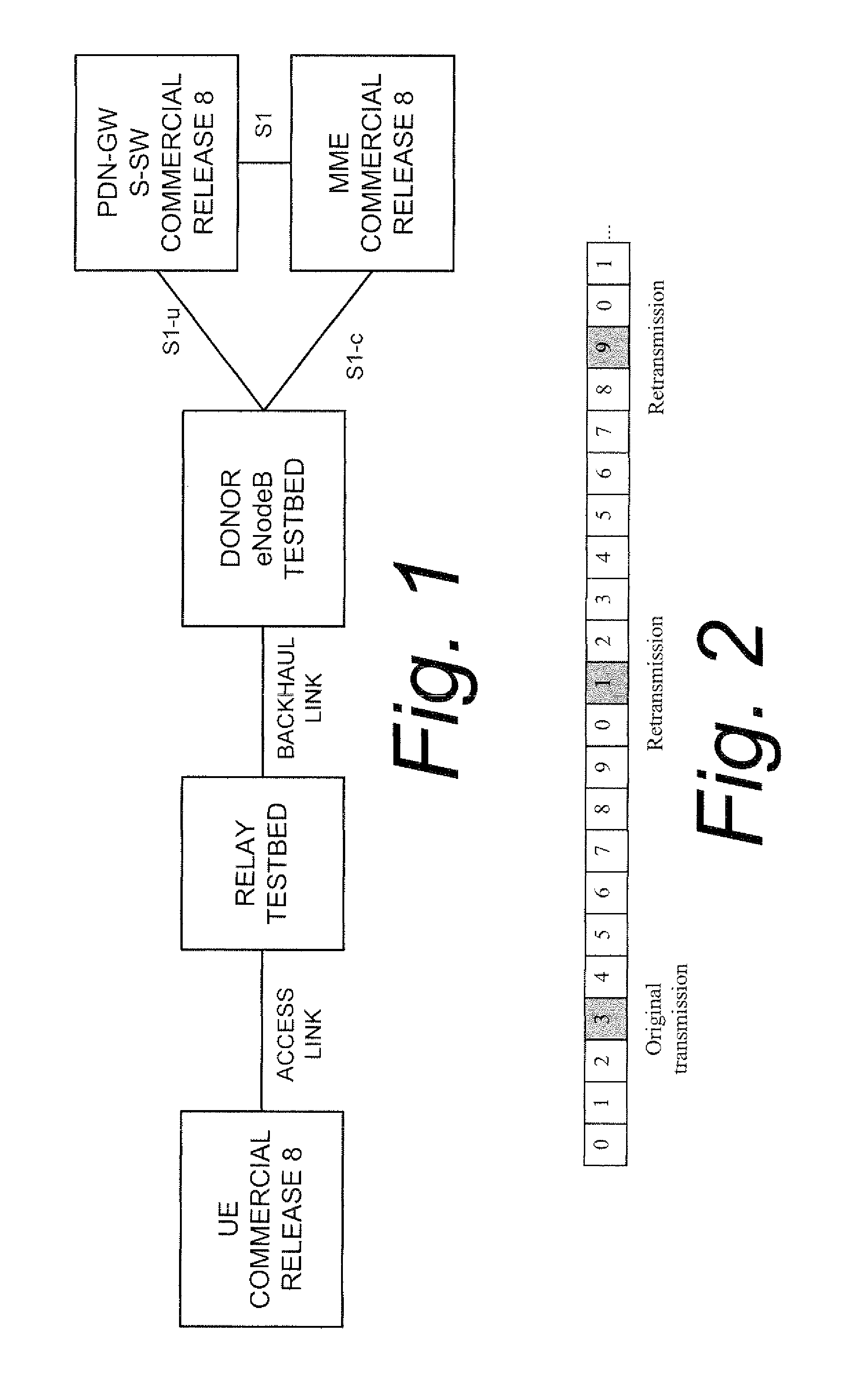
In accordance with an aspect of the technology disclosed herein, within a regular non-MBSFN DL subframe, the relay node switches between transmit and receive mode making it possible to transmit certain mandatory signals from the relay while in the same subframe receiving certain control information and / or data over the backhaul from the donor eNodeB, without causing TX / RX self-interference in the relay node.

Problems solved by technology

Since both the reception from the donor base station node and the transmission to the wireless terminal (UE) involve the same frequency band, a problem with inband relays is avoidance of self-interference from transmitting antennas to receiving antennas in the relay node.
However, a problem with time multiplexing is that 3GPP specifications allow wireless terminals (UE) to normally assume that the base station transmits certain physical signals in each subframe, meaning that the relay node needs to transmit in each subframe.
The possibilities for specifying some subframes as “MBSFN” are limited.

Method used


Image

  • Intra-subframe time multiplexing
  • Intra-subframe time multiplexing
  • Intra-subframe time multiplexing

Examples


Embodiment Construction

In the following description, for purposes of explanation and not limitation, specific details are set forth such as particular architectures, interfaces, techniques, etc. in order to provide a thorough understanding of the present invention. However, it will be apparent to those skilled in the art that the present invention may be practiced in other embodiments that depart from these specific details. That is, those skilled in the art will be able to devise various arrangements which, although not explicitly described or shown herein, embody the principles of the invention and are included within its spirit and scope. In some instances, detailed descriptions of well-known devices, circuits, and methods are omitted so as not to obscure the description of the present invention with unnecessary detail. All statements herein reciting principles, aspects, and embodiments of the invention, as well as specific examples thereof, are intended to encompass both structural and functional equi...


PUM


Abstract

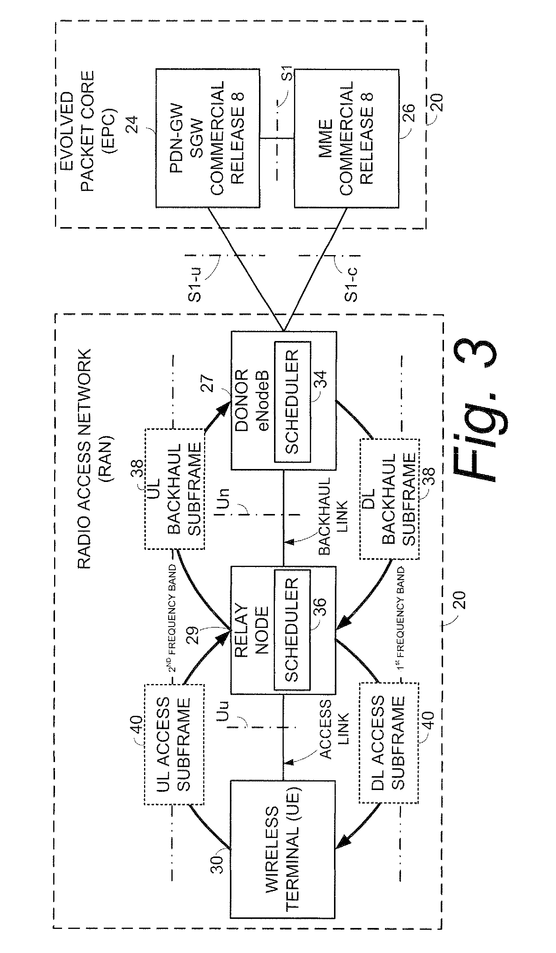
A relay node (29) radio access network (RAN) is configured to communicate using backhaul subframes over a Un radio interface with a donor base (27) station node and to communicate using access subframes over a Uu radio interface with a wireless terminal (30). Downlink backhaul subframes and downlink access subframes are transmitted over an air interface using the same frequency band, but a beginning of a selected downlink access subframe precedes a beginning of a next-in-time downlink backhaul subframe by a downlink timing advance (TA). The relay node (29) both receives downlink control information from the donor base station node and transmits downlink control information to the wireless terminal during the downlink backhaul subframe, e.g., during a time to which the downlink backhaul subframe has been allocated.

Description

BACKGROUNDThis invention pertains to telecommunications, and particularly to generation and handling of frames for single-frequency networksIn a typical cellular radio system, wireless terminals (also known as mobile stations and / or user equipment units (UEs)) communicate via a radio access network (RAN) to one or more core networks. The wireless terminals can be mobile stations or user equipment units (UE) such as mobile telephones (“cellular” telephones) and laptops with wireless capability (e.g., mobile termination), and thus can be, for example, portable, pocket, hand-held, computer-included, or car-mounted mobile devices which communicate voice and / or data via radio access network.The radio access network (RAN) covers a geographical area which is divided into cell areas, with each cell area being served by a base station, e.g., a radio base station (RBS), which in some networks is also called “NodeB” or “B node”. A cell is a geographical area where radio coverage is provided by...

Claims


Application Information

Patent Timeline
IPC IPC(8): H04B7/14
CPCH04B7/15542
Inventor WIBERG, NICLASANDERSSON, HAKANHOYMANN, CHRISTIAN
Owner TELEFON AB LM ERICSSON (PUBL)
Learn More