
Buckle

a technology for buckles and articles, applied in the field of buckles, can solve the problems of articles received in baggage or the camera connected to the buckles falling into the ground and suffering damage, and the second fastener may be removed from the first fastener undesirably,

Inactive Publication Date: 2011-05-12
GIOTTOS IND
View PDF13 Cites 18 Cited by
  • Summary
  • Abstract
  • Description
  • Claims
  • Application Information

AI Technical Summary

Benefits of technology

[0016]The first fastener has the locking piece moving in the socket to prevent the hooks of the second fastener from removing the first locking portions of the first fastener. When the first fastener is engaged with the second fastener, the locking piece is inserted into the second fastener to restrict the movement of the second fastener, so that the second fastener cannot be released unless the locking piece is removed from the second fastener and the hooks of the second fastener are pressed. Thus, the second fastener can be released only when the locking piece is moved, thereby preventing a problem that the second fastener may be separated from the first fastener when the hooks of the second fastener are incautiously pressed. A user has to move the locking piece with one hand and presses the hooks with another hand. Thus, such an action performed by two hands is uneasy for a child, thereby generating a safety effect.

Problems solved by technology

However, the user may incautiously press the portion of the hook of the second fastener protruding from the locking portions of the first fastener, so that the second fastener may be removed from the first fastener undesirably.
Especially when the buckle is used in a vertical orientation, the second fastener may slide out of the first fastener due to its gravity force.
As a result, the articles received in a baggage or the camera connected to the buckle may be fallen into the ground to suffer damage.

Method used


Image

  • Buckle
  • Buckle
  • Buckle

Examples


Embodiment Construction

[0025]The present invention will be described in more detail with reference to a preferred embodiment thereof shown in the accompanying drawings

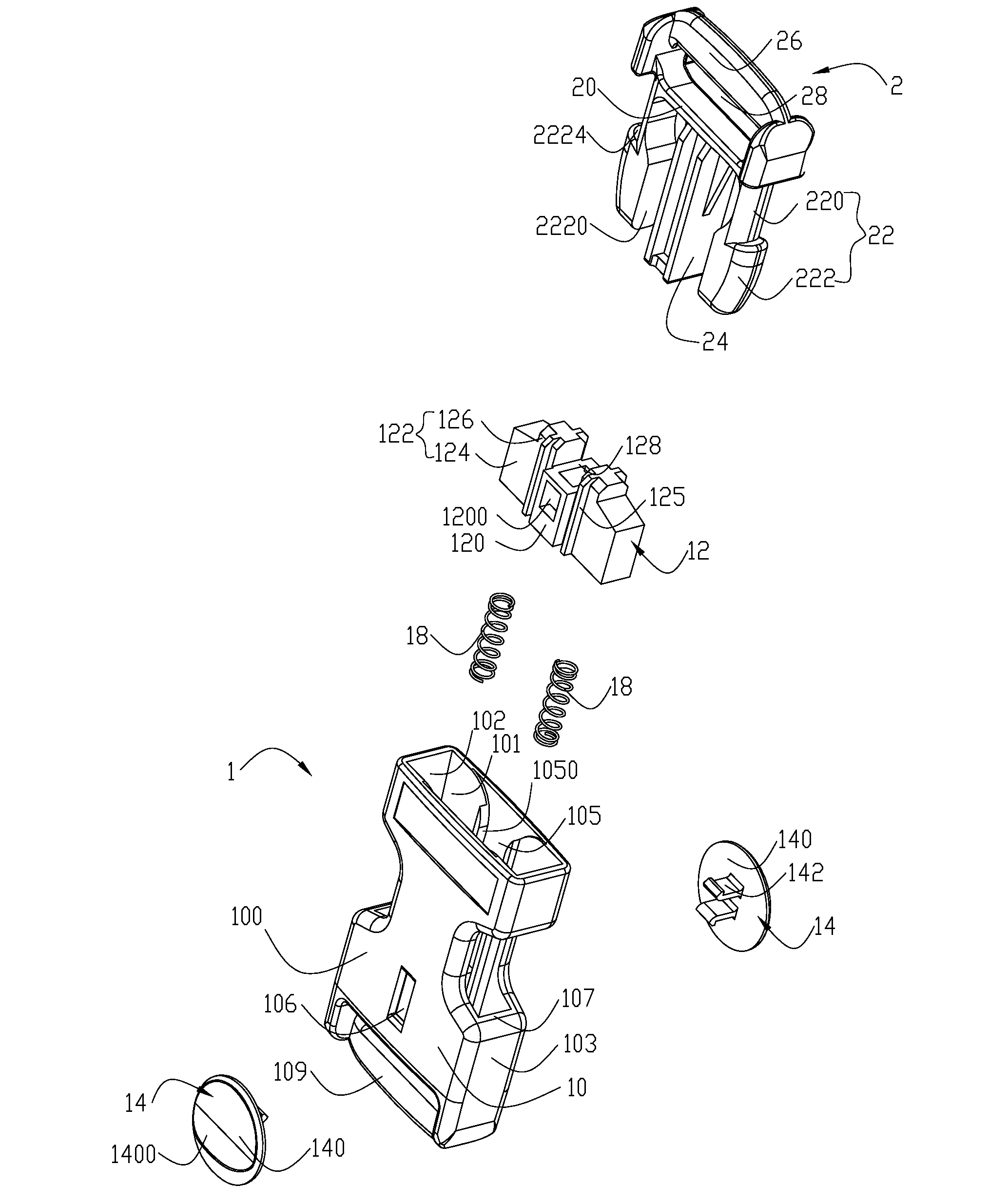
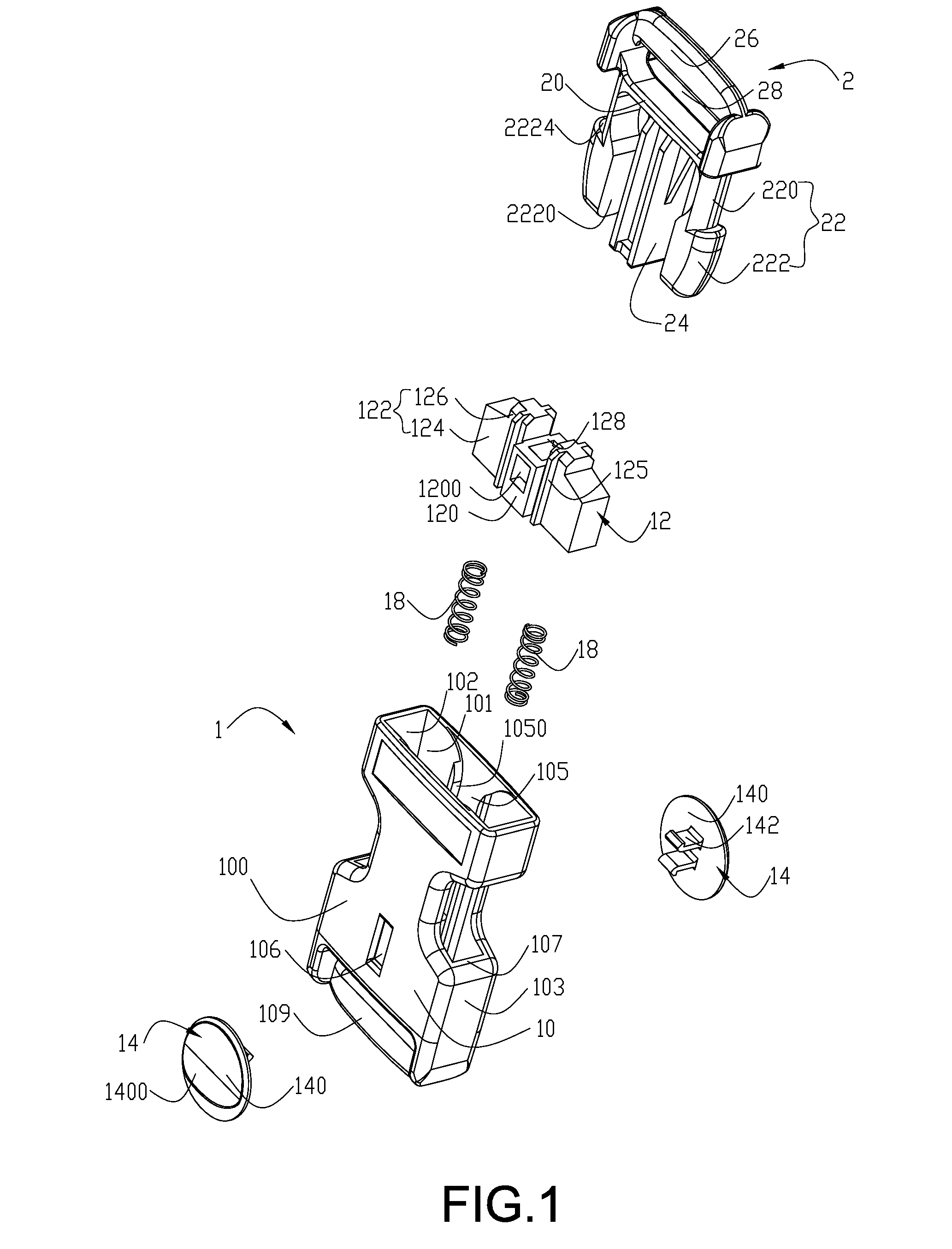
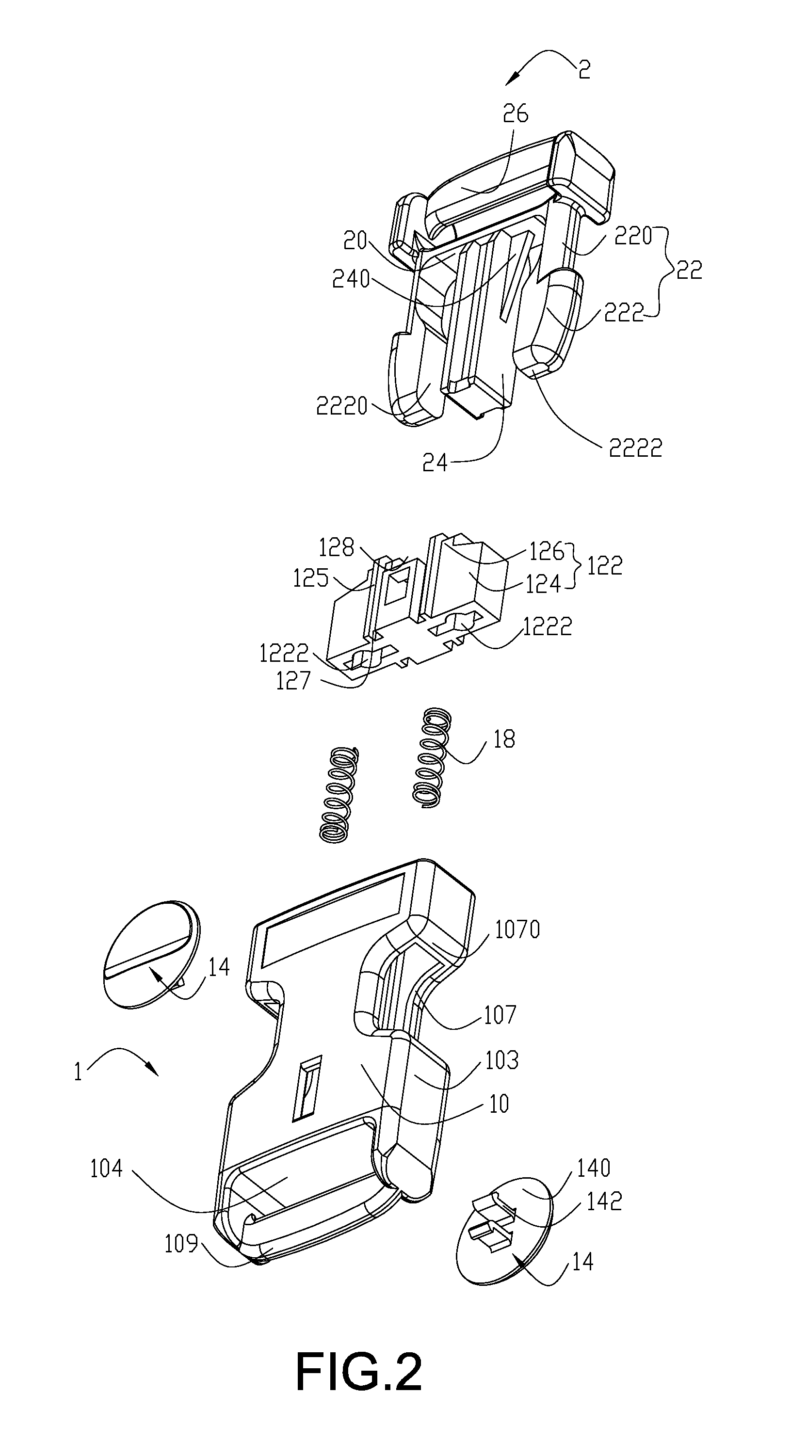
[0026]As shown in FIGS. 1 to 5. The buckle of the present invention includes a first fastener 1 and a second fastener 2 mating with the first fastener 1. The second fastener 2 includes a connecting wall 20, two hooks 22 formed on the connecting wall 20, a post 24 and a connecting piece 26 formed on the connecting wall 20.

[0027]The hooks 22 and the second connecting piece 26 are provided on both sides of the connecting wall 20, respectively. The second connecting piece 26 is formed on a distal end of each hook 22. A second elongate hole 28 is formed between the second connecting piece 26 and the connecting wall 20. The second connecting piece 26 is configured to connect to a belt. The belt passes through the second elongate hole 28 to be connected to the second connecting piece 26.

[0028]The hooks 22 are symmetrically formed on both ends of th...


PUM


Abstract

A buckle includes a first fastener and a second fastener. The second fastener has two hooks. The first fastener includes a socket, a locking piece disposed in the socket, and two first locking portions formed on the socket for mating with the hooks. The locking piece is slidingly connected in the socket to cooperate with the second fastener. When the first fastener is engaged with the second fastener, the locking piece enters the second fastener to restrict the movement of the second fastener, so that the second fastener cannot be released unless the locking piece is removed from the second fastener and the hooks of the second fastener are pressed. Thus, the second fastener can be released only when the locking piece is moved, thereby preventing a problem that the second fastener may be separated from the first fastener when the hooks of the second fastener are incautiously pressed. A user has to move the locking piece with one hand and presses the hooks with another hand. Thus, such an action performed by two hands is uneasy for a child, thereby generating a safety effect.

Description

BACKGROUND OF THE INVENTION[0001]1. Field of the Invention[0002]The present invention relates to an article for daily use, and in particular to a buckle.[0003]2. Description of Prior Art[0004]In general, when two ends of a belt of a camera, baggage or other device are needed to be connected to or disconnected from each other quickly, two fasteners mating with each other are often used. The two fasteners are referred to as a first fastener and a second fastener respectively hereinafter. The second fastener can be inserted into the first fastener and engaged therewith. The combination of the first fastener and the second fastener is called a buckle. When the first fastener is connected with the second fastener, the second fastener is pressed by the first fastener, so that the second fastener can be inserted into the first fastener deeply. Then, hooks on both sides of the second fastener will be locked by locking portions on both sides of the first fastener respectively by means of the...

Claims


Application Information

Patent Timeline
IPC IPC(8): A44B11/25
CPCA44B11/2573A44B11/266Y10T24/45524Y10T24/45723Y10T24/45581Y10T24/45529Y10T24/45623Y10T70/5009
Inventor SHEN, WEI-HONG
Owner GIOTTOS IND
Learn More