Stirling engine

Inactive Publication Date: 2011-05-12
VKR HLDG AS
View PDF3 Cites 2 Cited by
  • Summary
  • Abstract
  • Description
  • Claims
  • Application Information

AI Technical Summary

Benefits of technology

[0007]This is achieved in accordance with the invention in such a way that the oscillating lever is connected in an articulated manner with its first end to the connecting rod, it is pivotably mounted at its second end in the cylinder housing, and the first connecting rod is connected in an articulated manner between the first and second end. The relevant aspect in the present invention is the fact that as a result of the changed geometry of the crank drive a lower dwell time of the piston is achieved in the upper dead centre, in combination with a simultaneous faster movement in the region of the bottom dead centre. It is thus possible to achieve higher efficiencies. A further advantage of the present invention lies in the manner of introduction of forces on to the piston.
[0008]As a result of this kind of connection of the piston with the crankshaft, virtually no lateral forces act upon the piston, so that the realization of larger piston diameters and, consequently, a larger cylinder volume are enabled. A higher gas volume also means higher efficiency.
[0009]In a preferred embodiment of the invention, the oscillating lever comprises two sections which are aligned at an angle in relation to one another, with preferably the first connecting rod being connected in an articulated manner to the longer section. This arrangement of the oscillating lever allows an especially compact configuration of the Stirling machine.
[0010]In order to further reduce the lateral forces acting upon the piston, the end of the longer section of the oscillating lever advantageously comprises two projections via which the oscillating lever is connected in an articulated manner with the cylinder housing.
[0011]In an especially preferred embodiment of the invention, the oscillating lever is arranged in an integral manner. This reduces the number of the individual parts of the oscillating lever, which again extends the service life of the oscillating lever and reduces its production costs.
[0012]A further increase in the efficiency is achieved when the second connecting rod is provided with a short configuration, especially when its length is shorter than three times the crank throw. The shorter the connecting rod, the stronger a deviation from the sine progression of the piston movement and the higher the efficiency of the Stirling engine in accordance with the invention.

Problems solved by technology

It has been noticed that this movement pattern is relatively unfavourable for Stirling engines, leading to losses in the efficiency.
Moreover, the known solution has further disadvantages.
Since the pistons in a Stirling engine will always run dry in contrast to an internal combustion engine, these lateral forces have a highly negative effect, especially on the sealing behaviour and the service life of the pistons.

Method used


Image

  • Stirling engine
  • Stirling engine
  • Stirling engine

Examples


Embodiment Construction

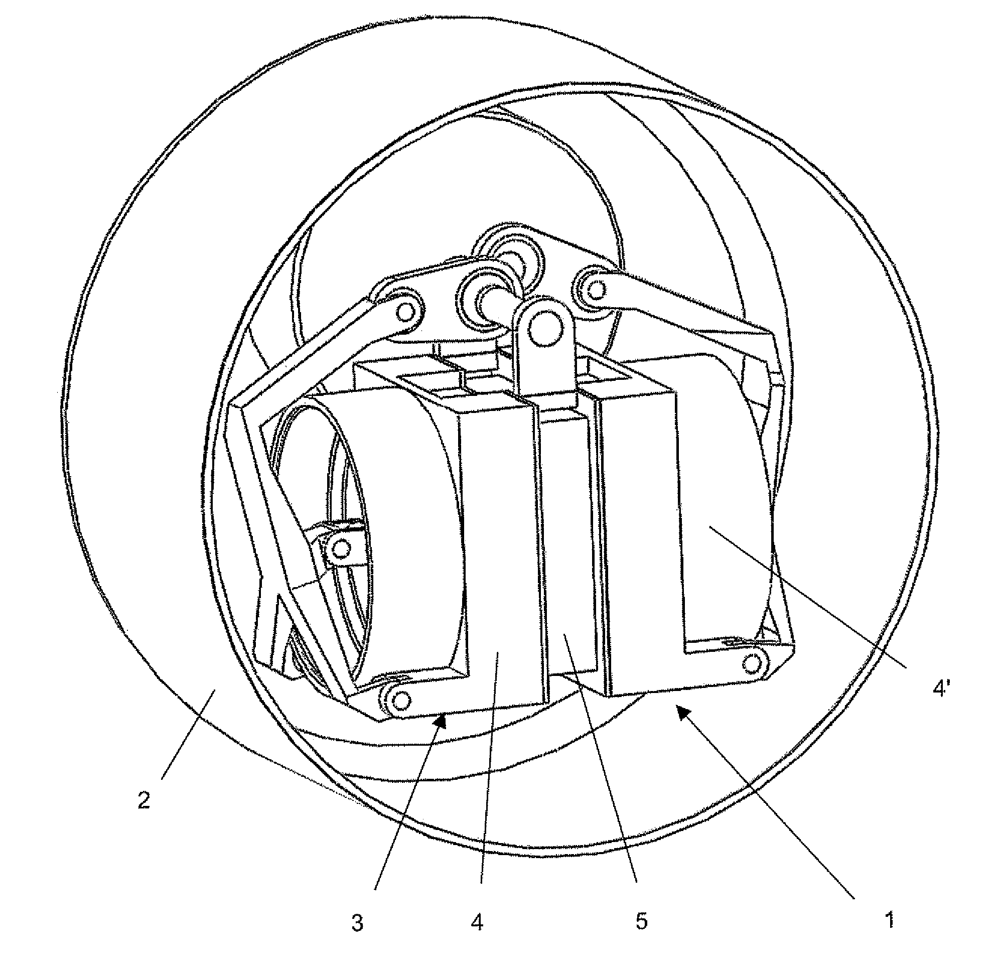
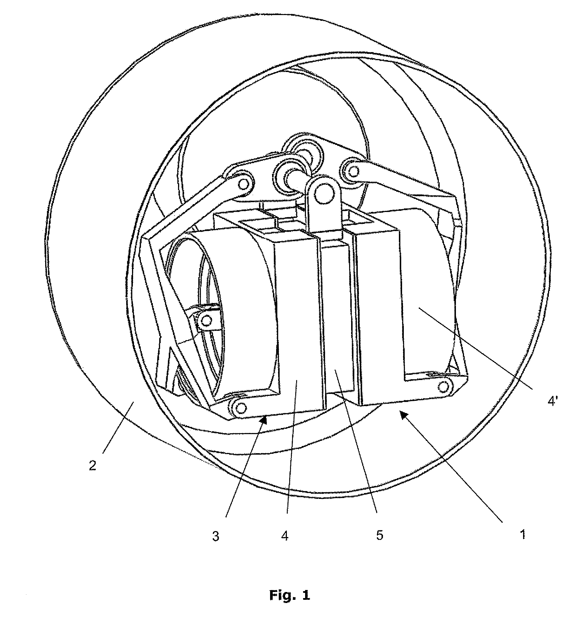
[0026]As is shown in FIG. 1, the Stirling engine 1 in accordance with the invention is housed in an engine housing 2 and comprises a cylinder housing 3 which is composed of two symmetrical cylinder halves 4, 4′. These identical cylinder halves 4, 4′ are connected with one another in a gas-tight manner via a connecting part 5.

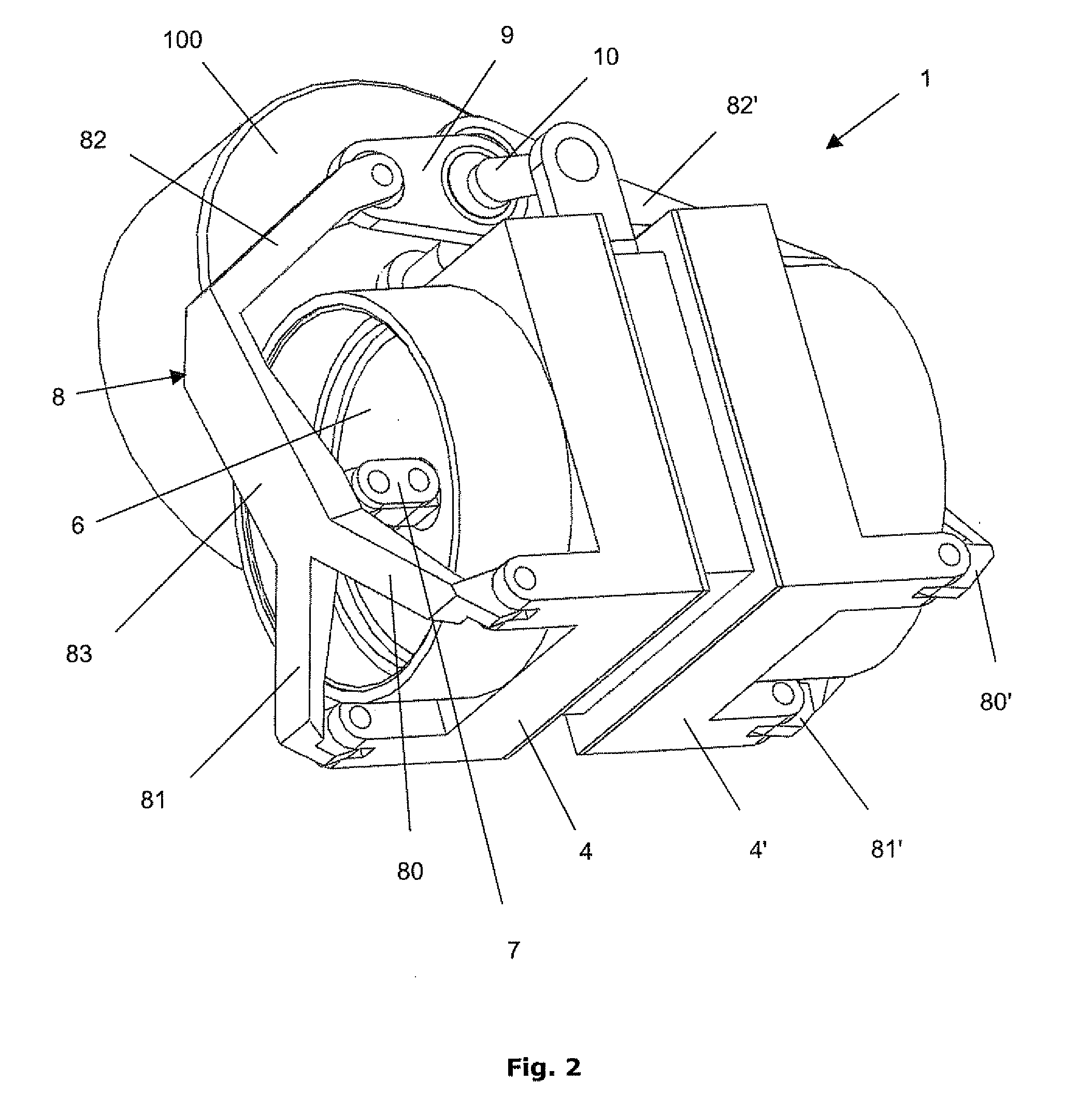
[0027]In accordance with FIGS. 2 and 3, a piston 6, 6′ is movably arranged in each cylinder half 4, 4′. The piston 6, 6′ is connected via a first connecting rod 7 with an oscillating lever 8, with the oscillating lever 8 ending in the illustrated embodiment of the invention in two projections 80, 81 at its end on the piston side. The oscillating lever 7 is pivotably mounted via these projections 80, 81 on the cylinder half 4.

[0028]The other end of the oscillating lever 8 is connected with a second connecting rod 9, which on its part is coupled with a crankshaft 10, with the crankshaft 10 driving a generator 100.

[0029]The oscillating lever 8, 8′ is integrally arr...


PUM


Abstract

The invention relates to a Stirling engine, including at least one cylinder in which two pistons are arranged which move counter to one another, with each piston being connected by means of a first connecting rod to an oscillating lever, and the oscillating lever is connected by means of a second connecting rod to the crankshaft, where the oscillating lever is connected in an articulated manner with its first end to the second connecting rod, it is pivotably mounted at its second end in the cylinder housing, and the first connecting rod is connected in an articulated manner between the first and second end.

Description

TECHNICAL FIELD[0001]The invention relates to a Stirling engine, comprising at least one cylinder in which two pistons are arranged which move counter to one another, with each piston being connected by means of a first connecting rod to an oscillating lever, and the oscillating lever is connected by means of a second connecting rod to the crankshaft.BACKGROUND[0002]A Stirling engine is a work machine in which heat is supplied from the outside to a cylinder, or is discharged by a cylinder. It is possible to operate the machine as an engine, with a working medium being cooled and heated in an alternating fashion in a cycle process in order to generate mechanical work. Conversely, a Stirling engine can also be used as a refrigerating machine, in which heat is brought from a lower temperature level to a higher temperature level by applying mechanical work. It is possible to cover both fields of application within the scope of the present invention.[0003]It is known to arrange Stirling ...

Claims


Application Information

Patent Timeline
IPC IPC(8): F02G1/057F02G1/053
CPCF02G1/044F02G1/053F02G2270/85F02G2270/45F02G2244/12
Inventor ENGELHART, KLAUS
Owner VKR HLDG AS
Why Eureka
Try Eureka