Aircraft seats and seating arrangement

Inactive Publication Date: 2011-05-12
BE AEROSPACE INCORPORATED
View PDF13 Cites 39 Cited by
  • Summary
  • Abstract
  • Description
  • Claims
  • Application Information

AI Technical Summary

Benefits of technology

[0007]It is another object of the present invention to provide an aircraft seating arrangement wherein the seat legs and the seat belt attachment points are placed in the same plane as the legs, thereby permitting the seating load to be carried more direct

Problems solved by technology

This may cause aisle and window passengers, for example, to have less

Method used


Image

  • Aircraft seats and seating arrangement
  • Aircraft seats and seating arrangement
  • Aircraft seats and seating arrangement

Examples


Embodiment Construction

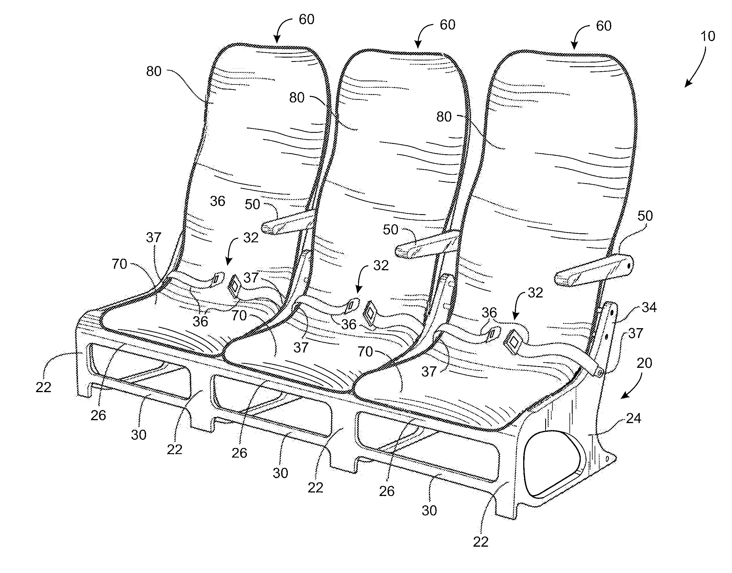
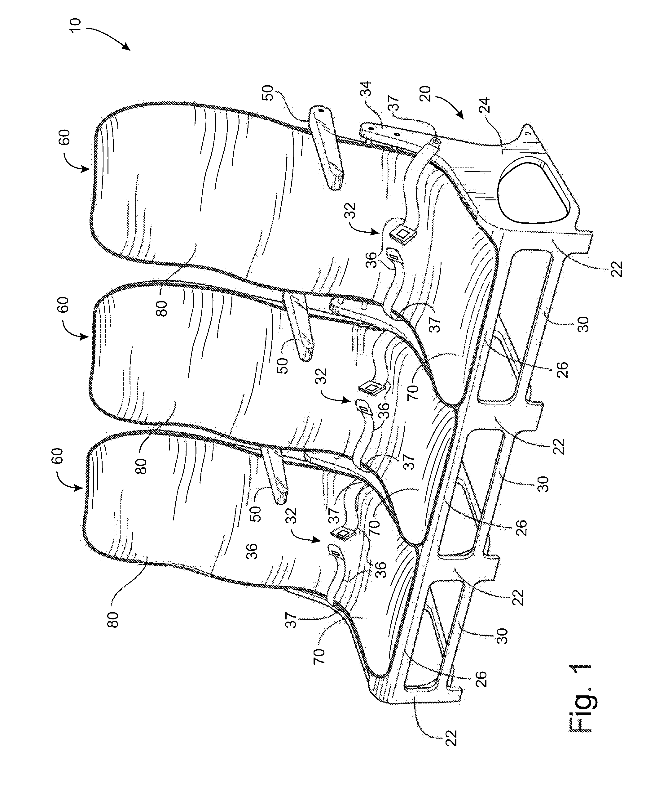
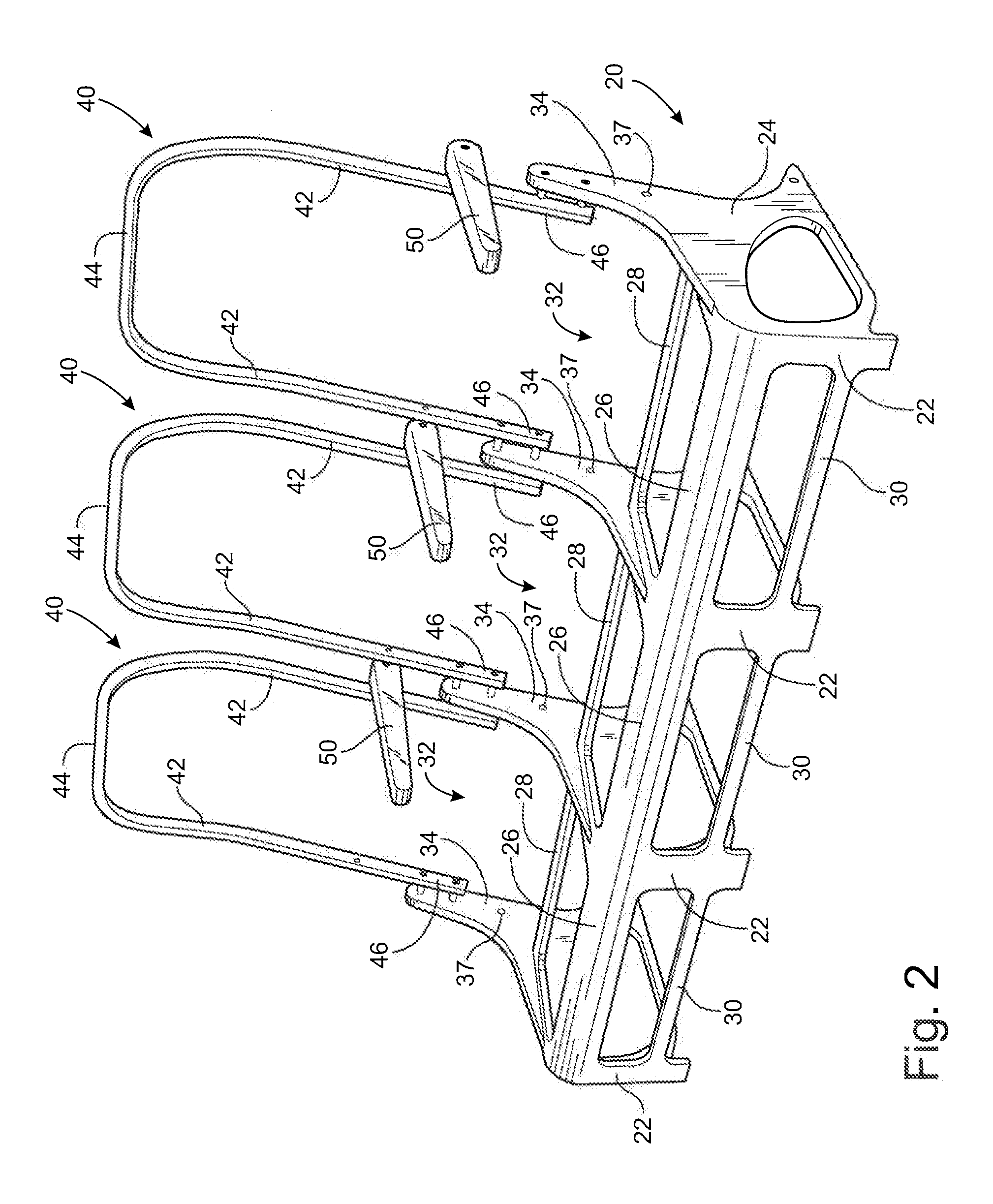
[0048]Referring now specifically to the drawings, FIG. 1 illustrates a passenger seating arrangement 10 for use on aircraft having a coach-class passenger cabin. The seating arrangement 10 is mounted in tracks extending along the length of a deck and secured to the tracks with conventional track fittings, not shown. FIGS. 1, 3, 5, 7, 9 and 11 show the seating arrangement 10 with its composite panels 60, each having a seat pan 70 and a back support 80. FIGS. 2, 4, 6, 8, 10 and 12 show the lower seat bottom frame 20 and multiple upper back-support frames 40 without the composite panels 60 to better show the constructions of the frames 20 and 40.

[0049]With particular reference now to FIGS. 2, 4, 6, 8, 10 and 12, the seat bottom frame 20 in the illustrated example is a one-piece, i.e., integrally-formed, structure formed of a composite material such as a carbon fiber textile material filled and coated with a hardened resin. Preferred fabrication techniques include “wet” layup and pre-im...


PUM


Abstract

An aircraft seating arrangement including a single-piece seat bottom frame having a plurality of laterally spaced-apart fore and aft legs for being attached to and supporting the seat frame on an aircraft deck and a plurality of seat bottoms supported on the seat frame. A plurality of seat back support frames are carried by the seat bottom frame aft of respective ones of the seat bottoms. A seat pan and seat back are positioned on respective seat bottoms and seat backs for passenger occupancy.

Description

TECHNICAL FIELD AND BACKGROUND OF THE INVENTION[0001]This invention relates generally to an aircraft seats and seating arrangement, and more particularly to aircraft passenger seating engineered to have reduced weight, improved load-bearing characteristics, enhanced storage space and improved ergonomics.[0002]A typical airline passenger seat has a back support carried by a lower seat frame supporting a seat bottom constructed of separately formed metal components. Weight of aircraft components is always an important factor in product selection and use because of the direct correlation between weight and fuel costs—a critical component in operating efficiency and total operating costs. Reduced seat weight and distribution not only achieves improved efficiency in the seat itself but also permits the weight of supporting deck structures to be reduced as well, resulting in substantial operating cost savings during the life of the seats. Single piece composite resin structures formed by ...

Claims


Application Information

Patent Timeline
IPC IPC(8): B64D11/06
CPCB64D11/06B64D11/0696B64D11/0636B64D11/0649B64D11/0646Y02T50/46Y02T50/40B64D11/0644B64D11/0643B64D11/062
Inventor POZZI, ALEXANDER NICHOLASPLANT, TOMMY GEORGE
Owner BE AEROSPACE INCORPORATED
Why Eureka
Try Eureka