
Surrounding Structure of Storage Compartment of Instrument Panel

Inactive Publication Date: 2011-05-12
SUZUKI MOTOR CO LTD
View PDF26 Cites 4 Cited by
  • Summary
  • Abstract
  • Description
  • Claims
  • Application Information

AI Technical Summary

Benefits of technology

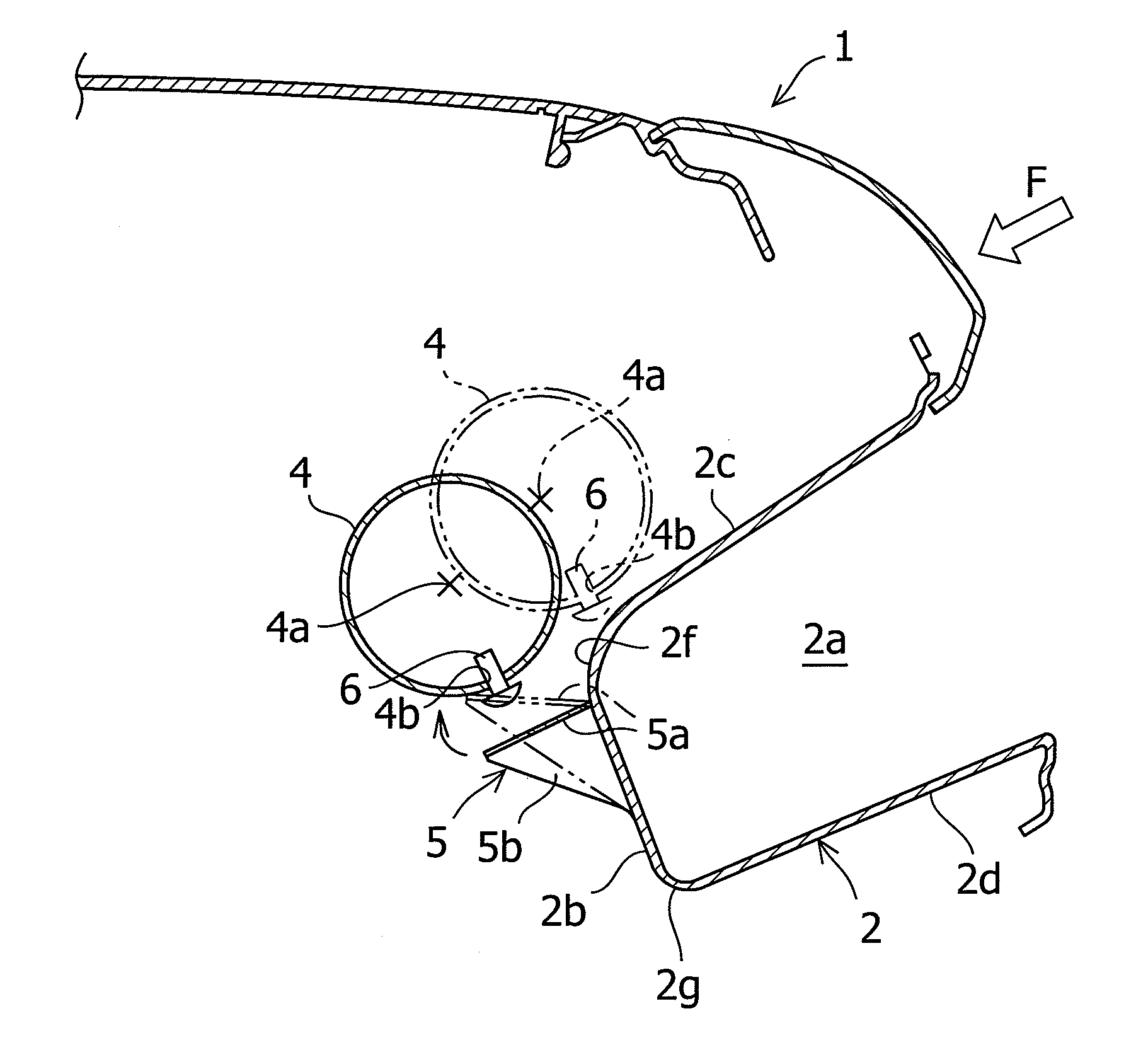
[0013]A surrounding structure of a storage compartment of an instrument panel according to the present invention, including the storage compartment formed in an instrument panel of a vehicle so as to be recessed toward a front of the vehicle, includes a steering support member extending in a vehicle width direction on a forward position of a front wall of the storage compartment, and an attachment piece protruding from the front wall toward the front of the vehicle. The attachment piece has an attachment portion abutting the steering support member, the attachment portion is provided with a U-shaped cutout part formed to be opened on a front edge or a rear edge of the attachment portion, the attachment piece is configured to be fastened to the steering support member by a fastening member inserted into the cutout part of the attachment portion, and a cross-sectional center of the steering support member is arranged above a top edge of the front wall or below a bottom edge of the front wall.
[0014]Accordingly, the storage compartment of the instrument panel is securely supported by the steering support member in the normal condition. When the force is applied from the inside of the vehicle cabin to the instrument panel in this normal condition, is transmitted to the storage compartment, and acts on the storage compartment, the storage compartment moves while deforming the attachment piece attached to the steering support member, or moves after uncoupling from the steering support member. Furthermore, since the cross-sectional center of the steering support member is arranged above the top edge of the front wall or below the bottom edge of the front wall, the storage compartment uncoupled from the steering support member, moves to a position below or above the steering support member. Therefore, the steering support member does not receive the force applied to the storage compartment, and the steering support member can make the force escape to the front of the vehicle. As a result, the force applied from the i

Problems solved by technology

However, in Japanese Patent Publication No. 3619072, since the upper tray of the I-panel is supported by the member in the condition of high rigidity, the force ap

Method used


Image

  • Surrounding Structure of Storage Compartment of Instrument Panel
  • Surrounding Structure of Storage Compartment of Instrument Panel
  • Surrounding Structure of Storage Compartment of Instrument Panel

Examples


Example

First Embodiment

[0025]A surrounding structure of a storage compartment of an instrument panel in a first embodiment of the present invention, is described as below.

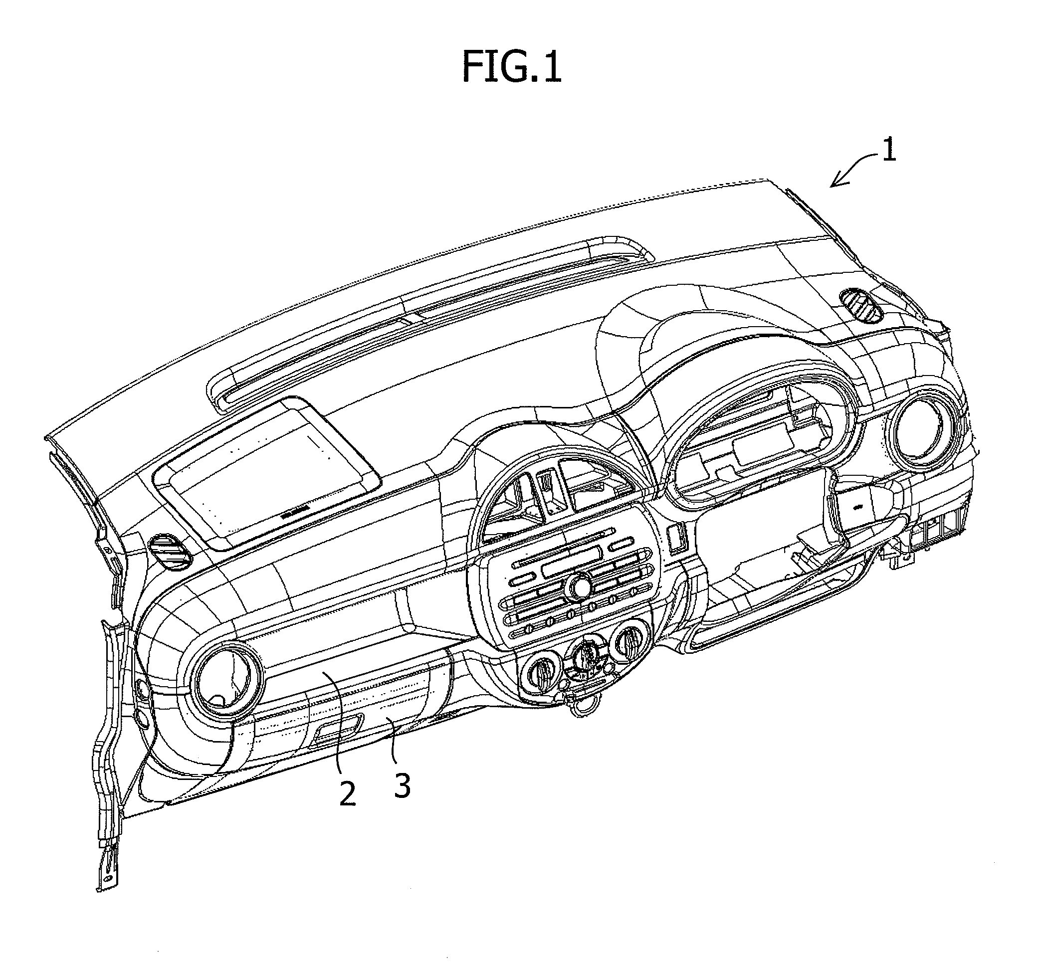
[0026]As shown in FIG. 1, an I-panel 1 is arranged in the front of a driver seat and a front passenger seat (not shown) in the vehicle. The I-panel 1 is manufactured with a resin molding. In the front of the front passenger seat, an upper tray 2 is arranged in the I-panel 1 as a storage compartment. The upper tray 2 is formed in a substantial box shape which is recessed toward the front of the vehicle. A glove box 3 is arranged below the upper tray 2.

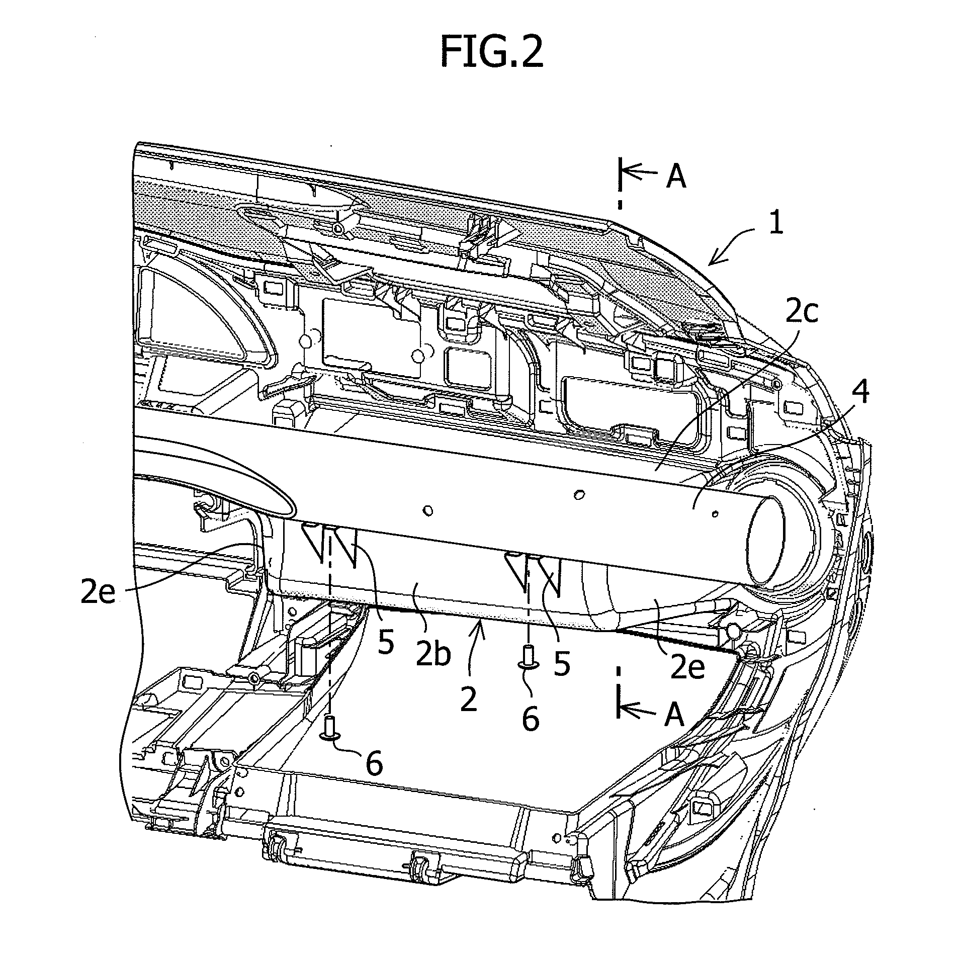
[0027]Referring to FIG. 2 and FIG. 3, the upper tray 2 has a front wall 2b, a top wall 2c, a bottom wall 2d, and paired side walls 2e, which define a storage space 2a inside of the upper tray 2. A border portion 2f between the front wall 2b and the top wall 2c, and a border portion 2g between the front wall 2b and the bottom wall 2d, are respectively formed to curve toward th...

Example

[0037]A second embodiment of the present invention is described below. The basic structure of the second embodiment is similar to that of the first embodiment. The same elements as those of the first embodiment are described using the same reference numerals and names given for the first embodiment. Hereinafter, a structure different from that of the first embodiment is described.

[0038]In the second embodiment, as shown in FIG. 6, an attachment piece 11 for attaching the S-member 4 is provided so as to protrude toward the front of the vehicle. The attachment piece 11 is provided with, on a top edge thereof, an attachment portion 11a extending in the same direction as the direction in which the upper tray 2 is recessed. The attachment portion 11a is arranged apart from the front wall 2b of the upper tray 2. The attachment portion 11a is formed continuous with the front wall 2b by triangular rib portions 11b extending between the front wall 2b and both vehicle-width-direction edges of...


PUM


Abstract

A surrounding structure of a recessed storage compartment of an instrument panel, including the compartment formed in the instrument panel, includes a steering support member extending in a vehicle width direction on a forward position of a front wall of the compartment, and an attachment piece protruding frontward from the front wall. The attachment piece has an attachment portion abutting the support member. A U-shaped cutout is formed in the attachment portion to be opened on a front edge of the attachment portion or on a rear edge of the attachment portion. The attachment piece is fastened to the support member by a fastening member inserted into the cutout. A cross-sectional center of the support member is arranged above a top edge or below a bottom edge of the front wall.

Description

FIELD OF THE INVENTION[0001]The present invention relates to a surrounding structure of a storage compartment of an instrument panel, which is supported by a steering support member in a vehicle.BACKGROUND OF THE INVENTION[0002]Typically, an instrument panel (hereinafter referred to as an “I-panel”) of a vehicle such as an automobile, or the like, is provided with a storage compartment such as a glove box, upper tray, or the like. This storage compartment is formed so as to be recessed toward a front of the vehicle, as seen from the inside of a vehicle cabin. In addition, a member extending in a vehicle width direction, is provided on the back side of the I-panel. In some cases, structures in which a front wall of the storage compartment and the I-panel are supported by this member, are adopted.[0003]For example, in Japanese Patent Publication No. 3619072, in order to support an upper tray constituting the storage compartment in the condition of high rigidity, and in order to suppor...

Claims


Application Information

Patent Timeline
IPC IPC(8): B60R7/06
CPCB62D25/145B60R7/06
Inventor MASADA, KEIICHIFUJITA, TOMONARI
Owner SUZUKI MOTOR CO LTD
Learn More