Liquid crystal display device

Inactive Publication Date: 2011-05-12
JAPAN DISPLAY INC +1
View PDF17 Cites 16 Cited by
  • Summary
  • Abstract
  • Description
  • Claims
  • Application Information

AI Technical Summary

Benefits of technology

[0017]It is an object of the present invention to provide a liquid crystal display device which can suppress the degradation of image quality more effectively than a case where the correction is made based on the difference in display tone.
[0026]According to the present invention, it is possible to provide the liquid crystal display device which can suppress the degradation of image quality more effectively than a case where the correction is made based on the difference in display tone.

Problems solved by technology

When the image data writing time becomes shorter, there arises a phenomenon where a potential applied to a pixel electrode is not sufficiently changed to a potential which allows a pixel circuit to display an original display tone shown by image data (writing shortage of image data).
The writing shortage of image data brings about the degradation of image quality such as a color shift of image data to be displayed originally.
However, there may be a case where the correction performed by this correction method is insufficient or brings about the excessive correction thus giving rise to degradation of image quality.

Method used


Image

  • Liquid crystal display device
  • Liquid crystal display device
  • Liquid crystal display device

Examples


first embodiment

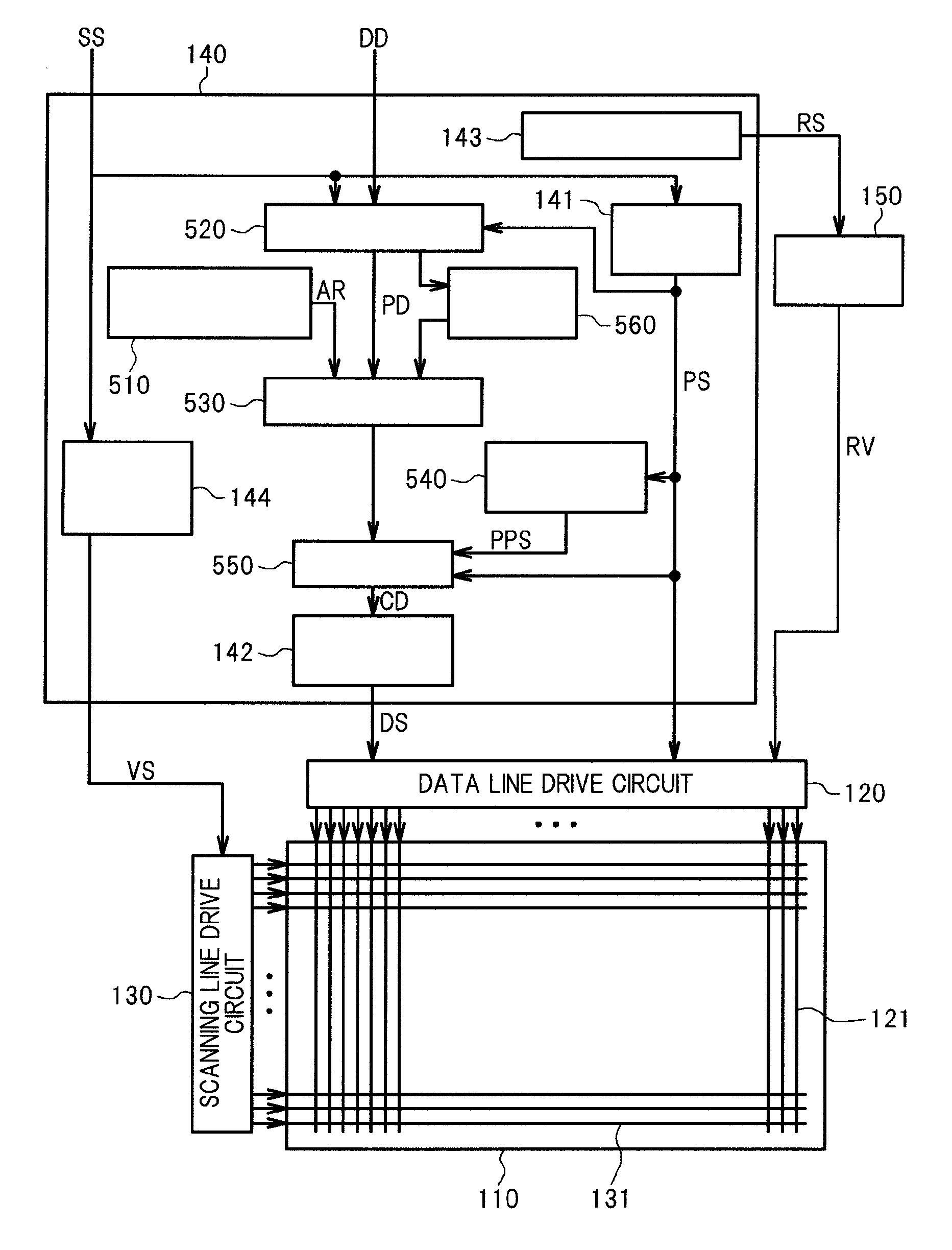
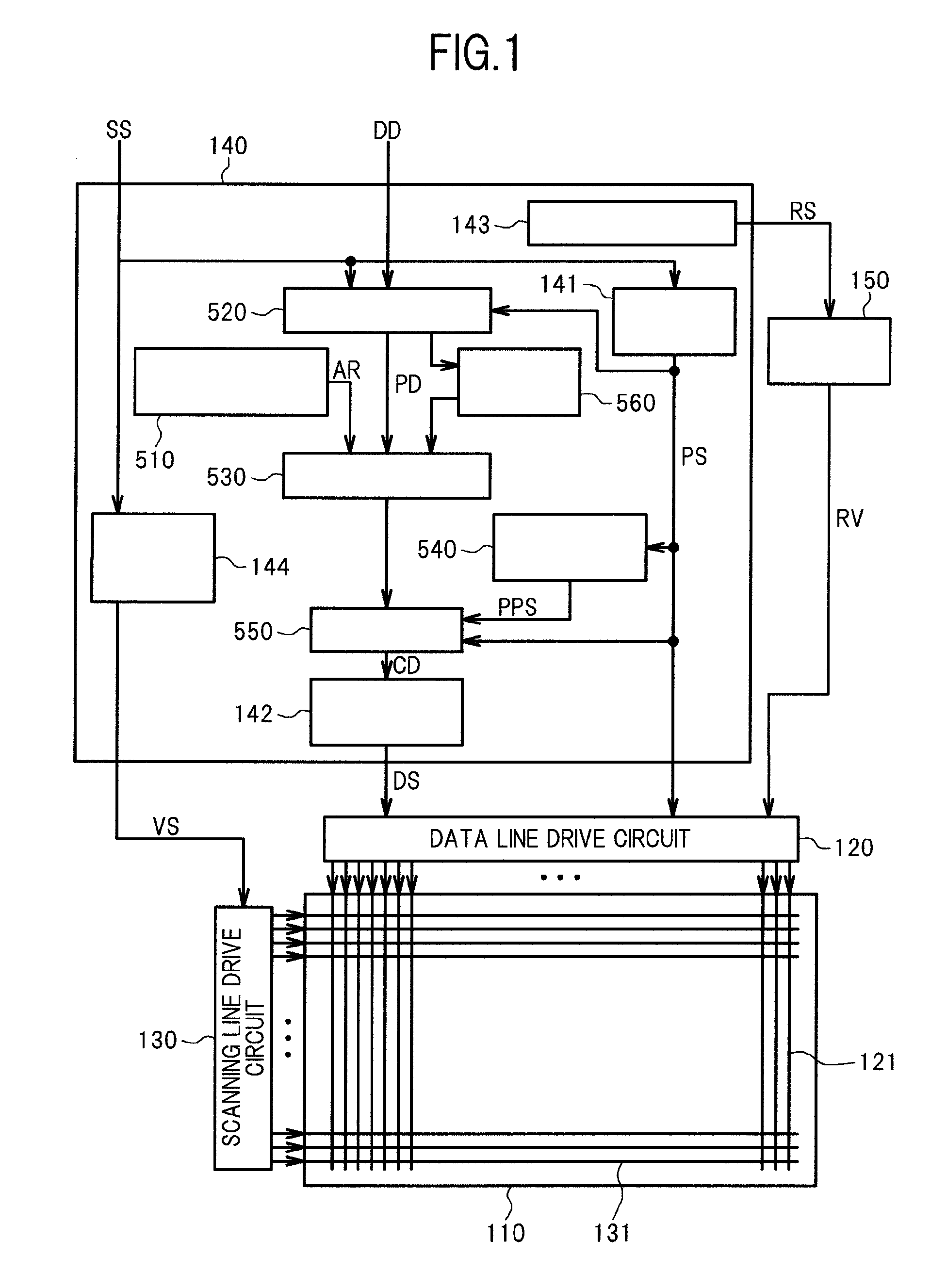
[0051]FIG. 1 shows an example of a liquid crystal display device according to a first embodiment of the present invention. The liquid crystal display device according to the first embodiment includes a liquid crystal display panel 110, a data line drive circuit 120, a scanning line drive circuit 130, and a control circuit 140. The liquid crystal display panel 110 is constituted of an array substrate and a counter substrate which is arranged to face the array substrate in an opposed manner. Liquid crystal is sealed in a space defined between the array substrate and the counter substrate. On the array substrate, a plurality of data lines 121 which extend in the longitudinal direction in the drawing and a plurality of scanning lines 131 which intersect with the data lines 121 and extend in the lateral direction in the drawing are formed. A region which is surrounded by two neighboring data lines 121 and two neighboring scanning lines 131 forms a pixel circuit for displaying one sub pix...

second embodiment

[0092]Hereinafter, a liquid crystal display device according to a second embodiment of the present invention is explained. The liquid crystal display device according to the second embodiment differs from the liquid crystal display device according to the first embodiment with respect to a point that a correction amount is changed based on a temperature of a liquid crystal display panel. Hereinafter, the explanation is made by mainly focusing on points which make this embodiment differ from the first embodiment.

[0093]FIG. 11 shows an example of the liquid crystal display device according to the second embodiment of the present invention. A control circuit 140 of the liquid crystal display device according to this embodiment includes a polarity signal generation part 141, a data line control signal generation part 142, a reference voltage control part 143, a scanning line control signal generation part 144, a tone potential arrival rate output circuit 510, a tone potential calculatio...

third embodiment

[0096]Hereinafter, a liquid crystal display device according to a third embodiment of the present invention is explained. The liquid crystal display device according to the third embodiment differs from the liquid crystal display device according to the second embodiment with respect to a point that the liquid crystal display device has a frame rate conversion function. Hereinafter, the explanation is made by mainly focusing on points which make this embodiment differ from the second embodiment.

[0097]FIG. 12 shows an example of the liquid crystal display device according to the third embodiment of the present invention. A control circuit 140 of the liquid crystal display device according to this embodiment includes a polarity signal generation part 141, a data line control signal generation part 142, a reference voltage control part 143, a scanning line control signal generation part 144, a tone potential arrival rate output circuit 510, a tone potential calculation circuit 520, a t...


PUM


Abstract

A liquid crystal display device includes data lines, a plurality of pixel circuits, and a control circuit which obtains data line potentials which are formed by correcting potentials which allow the respective pixel circuits to display tones. The control circuit obtains the data line potentials such that a correction amount from a first potential to the data line potential when a tone potential in a frame which is displayed is the first potential and a tone potential in a frame right before the frame is a second potential, and a correction amount from the second potential to the data line potential when the tone potential of the frame which is displayed is the second potential and the tone potential of the frame right before the frame is the first potential differ from each other.

Description

CLAIM OF PRIORITY[0001]The present application claims priority from Japanese application JP 2009-257473 filed on Nov. 10, 2009, the content of which is hereby incorporated by reference into this application.BACKGROUND OF THE INVENTION[0002]1. Field of the Invention[0003]The present invention relates to a liquid crystal display device.[0004]2. Description of the Related Art[0005]Recently, a liquid crystal display device has been popularly used in a television receiver set, a monitor of a personal computer or the like. FIG. 13 shows a constitutional example of a conventional liquid crystal display device. The liquid crystal display device includes a liquid crystal display panel 110, a data line drive circuit 120, a scanning line drive circuit 130, and a control circuit 140. The liquid crystal display panel 110 is constituted of an array substrate and a counter substrate. On the array substrate, a plurality of data lines 121 which extend in the longitudinal direction in the drawing and...

Claims


Application Information

Patent Timeline
IPC IPC(8): G09G3/36G09G5/10
CPCG09G3/3648G09G3/3685G09G2340/16G09G2320/041G09G2320/0252
Inventor OWA, MISAMARUYAMA, JUNICHITOSHIMA, GOKIOOISHI, YOSHIHISA
Owner JAPAN DISPLAY INC
Why Eureka
Try Eureka