Image processing apparatus and image processing method

Inactive Publication Date: 2010-04-29
CANON KK
View PDF53 Cites 4 Cited by
  • Summary
  • Abstract
  • Description
  • Claims
  • Application Information

AI Technical Summary

Benefits of technology

[0009]The present invention has been made to solve the above-described problems, and provides an image processing apparatus and image processing method for outputting a high-quality image by suppressing degradation of the image quality when a plurality of pixels are averaged to reduce the processing load of tone level conversion.
[0014]With this arrangement, the present invention can output a high-quality image by suppressing degradation of the image quality when a plurality of pixels are averaged to reduce the processing load of tone level conversion.

Problems solved by technology

However, it is difficult for general printers to reproduce a 256-level tone representation.
Depending on the image forming method of a printer, applying the multi-level error diffusion method may make unstable a dot around which no dot exits, that is, the dot of an isolated pixel.
However, processing to collect pixels within a block is complicated and increases the processing load.
However, the conventional method of performing error diffusion processing after averaging n adjacent pixels may lose information of an original image upon averaging if the density difference between the n pixels is large.
In this case, for example, the edge blurs, degrading an output image after error diffusion processing.

Method used


Image

  • Image processing apparatus and image processing method
  • Image processing apparatus and image processing method
  • Image processing apparatus and image processing method

Examples


first embodiment

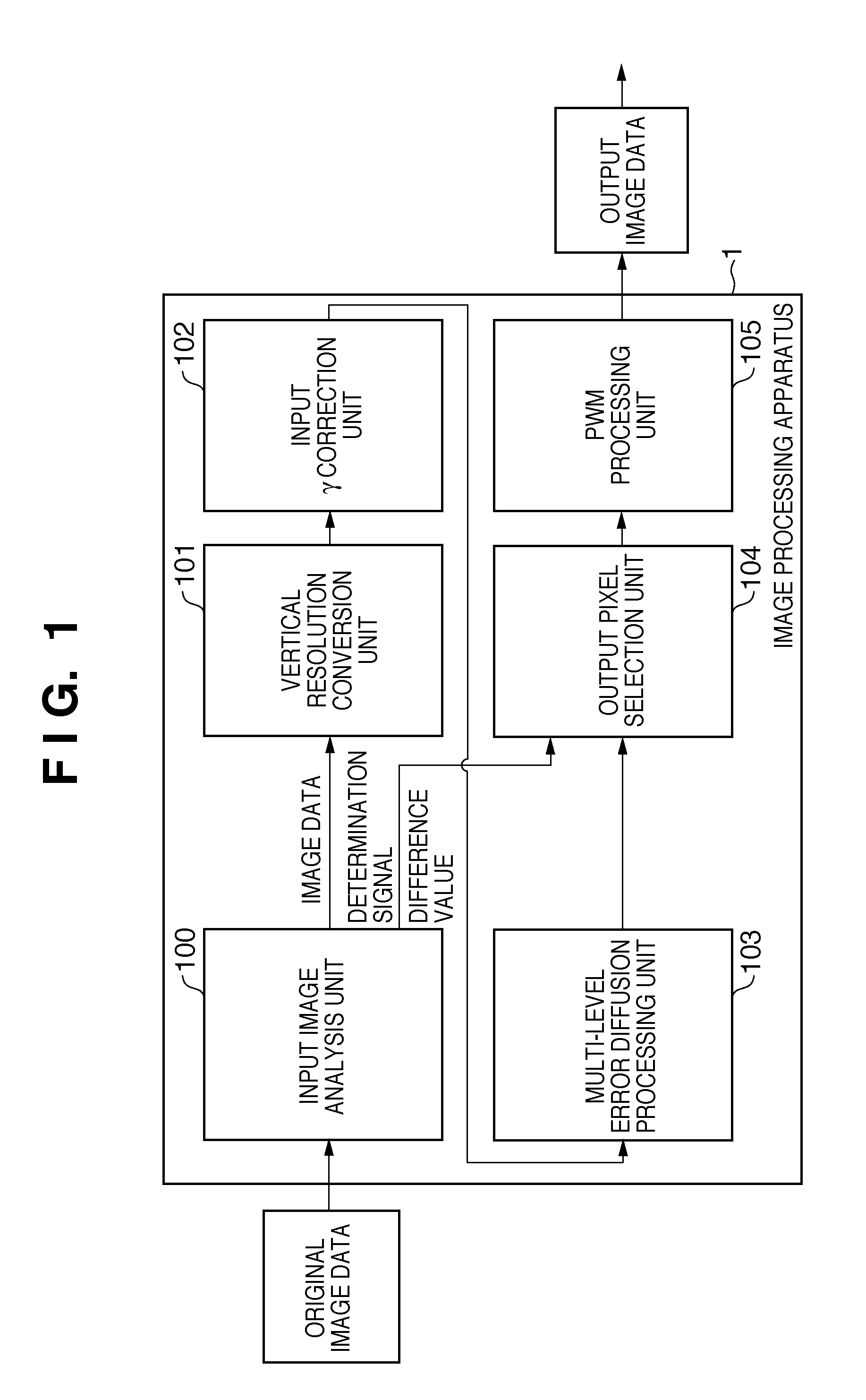
[0029]FIG. 1 is a block diagram showing the arrangement of an image processing apparatus 1 according to the first embodiment. As shown in FIG. 1, the image processing apparatus 1 in the first embodiment includes an input image analysis unit 100, vertical resolution conversion unit 101, input γ correction unit 102, multi-level error diffusion processing unit 103, output pixel selection unit 104, and PWM processing unit 105. The input image analysis unit 100 is connected to the vertical resolution conversion unit 101 and output pixel selection unit 104. The vertical resolution conversion unit 101 is connected to the input γ correction unit 102, and the input γ correction unit 102 is connected to the multi-level error diffusion processing unit 103. The multi-level error diffusion processing unit 103 is connected to the output pixel selection unit 104, and the output pixel selection unit 104 is connected to the PWM processing unit 105. With this arrangement, the image processing apparat...

second embodiment

[0056]The second embodiment according to the present invention will be described.

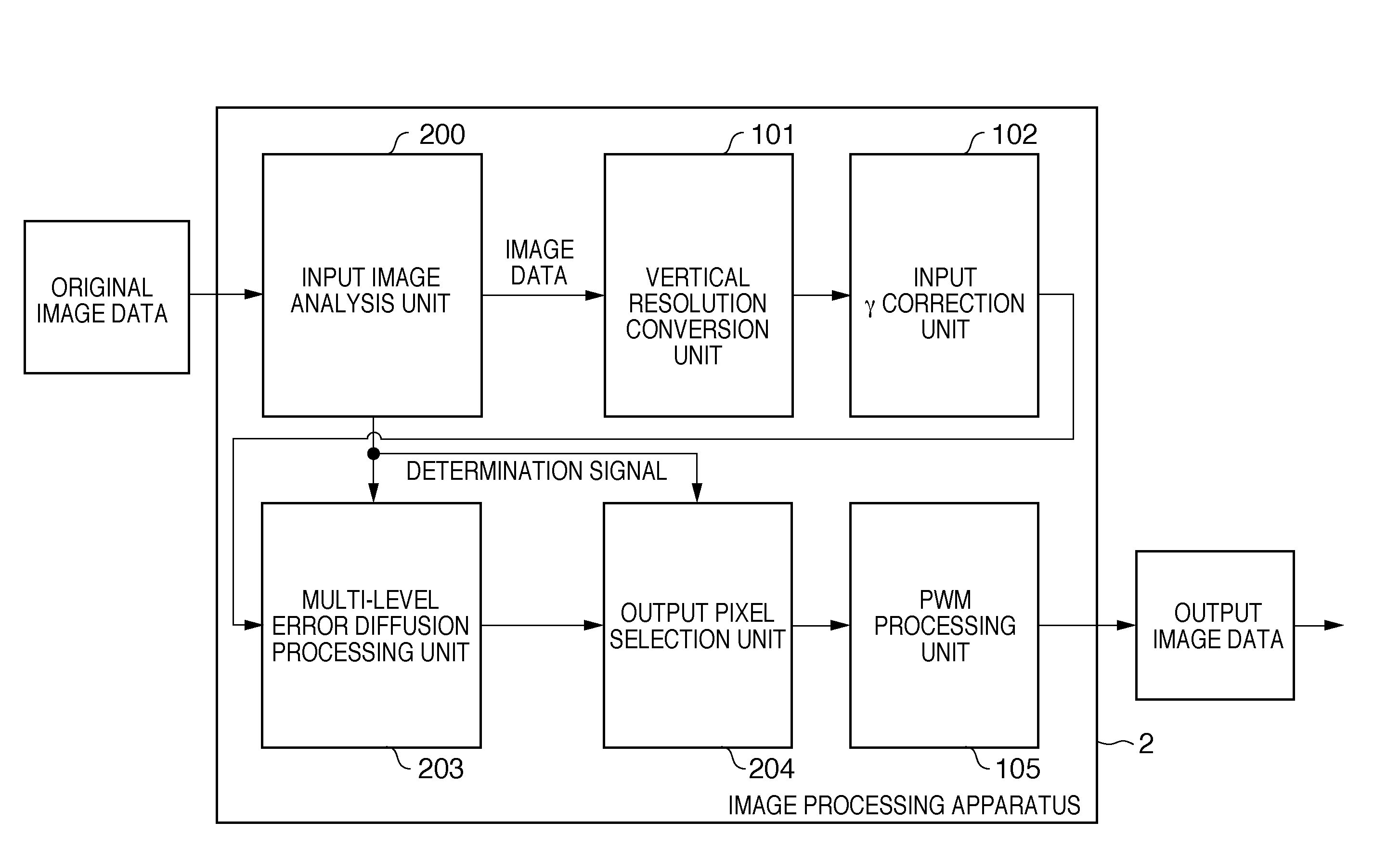
[0057]FIG. 8 is a block diagram showing the arrangement of an image processing apparatus 2 according to the second embodiment. As shown in FIG. 8, the image processing apparatus 2 in the second embodiment has almost the same arrangement as that of the image processing apparatus 1 in the first embodiment. The second embodiment is different from the first embodiment in the operations of an input image analysis unit 200, multi-level error diffusion processing unit 203, and output pixel selection unit 204.

[0058]The input image analysis unit 200 generates a 2-bit determination signal based on a difference value in a pixel block, similar to the first embodiment, and outputs only the determination signal to the multi-level error diffusion processing unit 203 and output pixel selection unit 204. The structure of the determination signal is the same as that in the above-described first embodiment. In the second ...


PUM


Abstract

An input image analysis unit (100) analyzes the difference value between two pixels adjacent in the subscanning direction in an input image having the first number of tone levels. A vertical resolution conversion unit (101) averages the two pixels to generate average image data. A multi-level error diffusion processing unit (103) performs tone level conversion for the average image data to generate low-level image data. An output pixel selection unit (104) selects two output pixel values for each pixel of the low-level image data based on the analysis result of the input image analysis unit (100), thereby creating output image data having the second number of tone levels.

Description

BACKGROUND OF THE INVENTION[0001]1. Field of the Invention[0002]The present invention relates to an image processing apparatus and image processing method and, more particularly, to an image processing apparatus and image processing method for performing tone level conversion by an error diffusion method.[0003]2. Description of the Related Art[0004]In general, an image is digitally represented using multiple tone levels such as 256 levels. In particular, a color image is represented at multiple tone levels for each of R, G, and B color components or C, M, Y, and K color components.[0005]However, it is difficult for general printers to reproduce a 256-level tone representation. Therefore, such printers adopt halftoning to convert multiple tone levels such as 256 levels into a smaller number of tone levels (for example, two or four levels) representable by a printer. A known example of the tone level conversion method is a multi-level error diffusion method capable of representing a 2...

Claims


Application Information

Patent Timeline
IPC IPC(8): G06K15/00
CPCH04N1/4056H04N1/4052H04N1/407
Inventor TAKAYAMA, YUUJIISHIKAWA, HISASHISAIKI, TOMOYUKIARAKI, GO
Owner CANON KK
Why Eureka
Try Eureka