Water Flow Monitor

a technology of water flow monitor and monitor, which is applied in the direction of fluid tightness measurement, valve operating means/release devices, instruments, etc., can solve the problems of water damage losses, damage to landscaping, adjacent structures, pool skirts and deckings,

Inactive Publication Date: 2011-05-19
GOSECO JOHN
View PDF17 Cites 88 Cited by
  • Summary
  • Abstract
  • Description
  • Claims
  • Application Information

AI Technical Summary

Problems solved by technology

Water damage losses are one of the biggest costs for insurance companies.
Additionally, fresh water is a limited resource that may be wasted when a pipe breaks and water runs for da

Method used


Image

  • Water Flow Monitor
  • Water Flow Monitor

Examples


Embodiment Construction

Description of Apparatus

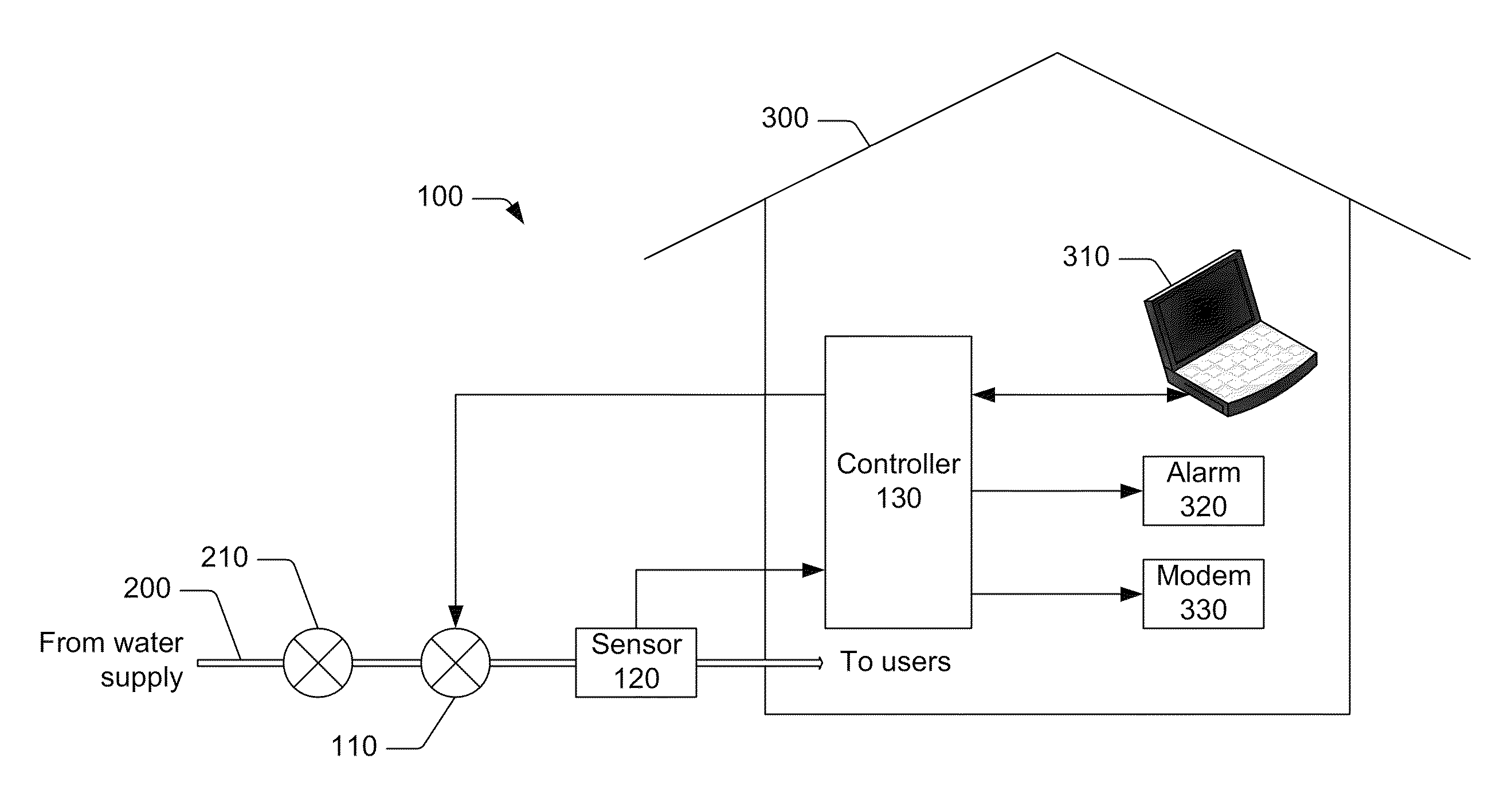
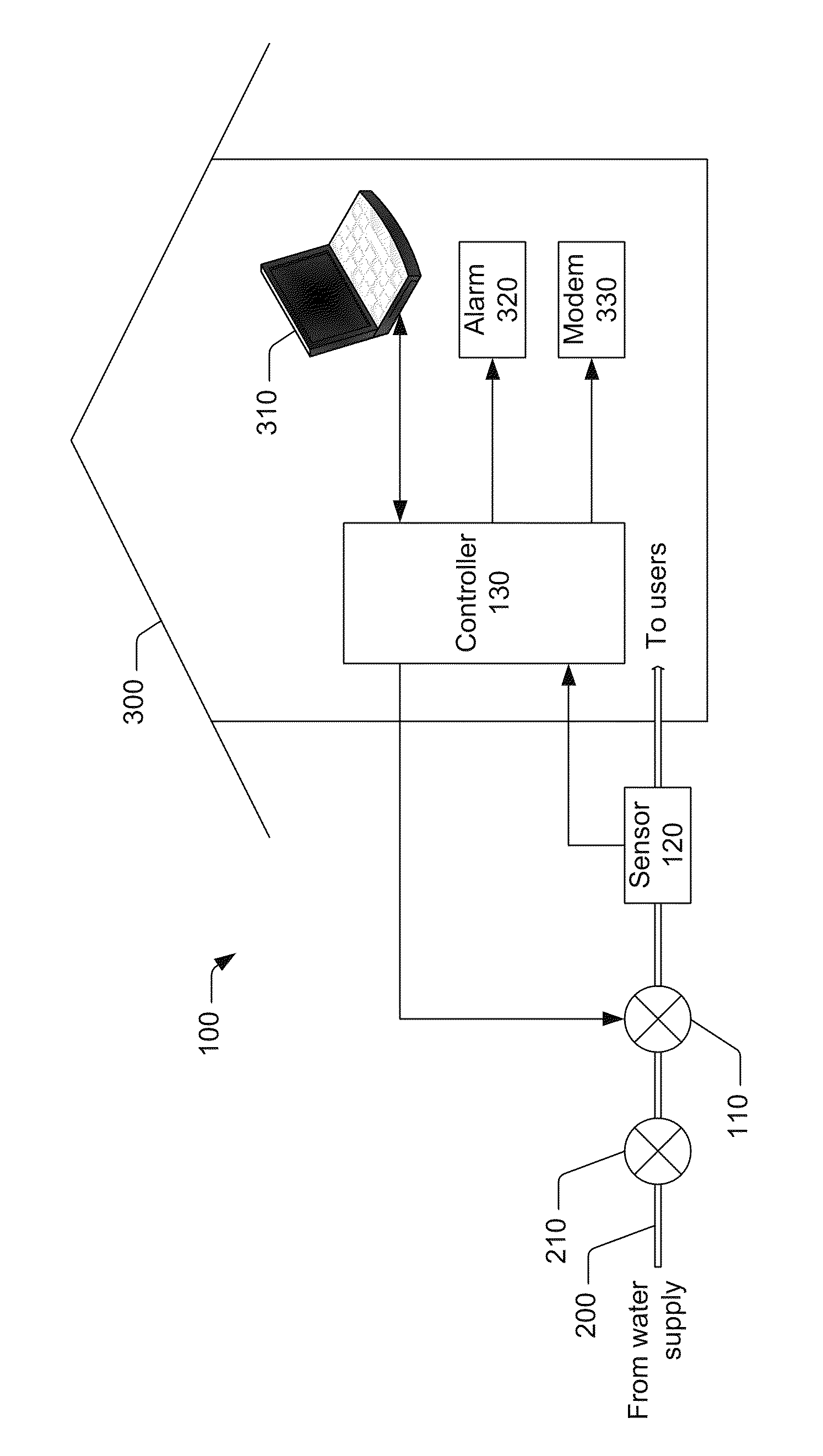
[0008]The FIGURE shows a water use monitoring and control system 100. The system 100 may include a controllable shut-off valve 110 disposed along a water supply line 200 that brings water to an establishment 300. The establishment 300 may be a house as shown, a business, a farm, or other user. The establishment 300 may be a recreational vehicle or a boat or other vehicle that has a plumbing system, in which case the water supply line 200 may connect to a water tank (not shown) within the vehicle. The water supply line 200 may be equipped with an existing manual shut-off valve 210. The controllable shut-off valve 110 may also be manually operable.

[0009]The system 100 may include a sensor 120 disposed along the water supply line 200 and a controller 130 coupled to the shut-off valve 110 and the sensor 120. The controller 130 may be located remotely from the shut-off valve 110 and / or the sensor 120. The controller 130 may be coupled to the shut-off valve 110 and...


PUM


Abstract

A system may include a controllable shut-off valve disposed in a water supply line and a water flow sensor disposed in the water supply line. A controller may be coupled to the shut-off valve and the sensor. The controller may be configured to receive information indicative of water flow from the sensor and to instruct the shut-off valve to shut off the water supply line in the event of unusual water usage.

Description

RELATED APPLICATION INFORMATION[0001]This patent claims priority from provisional patent application No. 61 / 261,202 filed on Nov. 13, 2009, entitled “WATER FLOW MONITOR”.NOTICE OF COPYRIGHTS AND TRADE DRESS[0002]A portion of the disclosure of this patent document contains material which is subject to copyright protection. This patent document may show and / or describe matter which is or may become trade dress of the owner. The copyright and trade dress owner has no objection to the facsimile reproduction by anyone of the patent disclosure as it appears in the Patent and Trademark Office patent files or records, but otherwise reserves all copyright and trade dress rights whatsoever.BACKGROUND[0003]1. Field[0004]This disclosure relates to monitor water usage.[0005]2. Description of the Related Art[0006]Water damage losses are one of the biggest costs for insurance companies. Additionally, fresh water is a limited resource that may be wasted when a pipe breaks and water runs for days if...

Claims


Application Information

Patent Timeline
IPC IPC(8): F16K31/02
CPCE03B7/04E03B7/10E03B7/071G01M3/2815Y10T137/7761Y02A20/15
Inventor GOSECO, JOHN
Owner GOSECO JOHN
Why Eureka
Try Eureka