Casing Annulus Management

a technology of casing annulus and casing, which is applied in the direction of sealing/packing, fluid removal, borehole/well accessories, etc., can solve the problem of limited communication between the outer annulus and the exterior of the wellhead assembly

Inactive Publication Date: 2011-05-19
VETCO GRAY
View PDF5 Cites 34 Cited by
  • Summary
  • Abstract
  • Description
  • Claims
  • Application Information

AI Technical Summary

Benefits of technology

Disclosed herein is a wellhead assembly that includes a pressure vent device that vents between concentric annuli when the pressure differential reaches or exceeds a pre-designated value. In an example embodiment the wellhead assembly includes an inner annulus set in a wellbore that is surrounded by an outer annulus. A tubular is between the inner and outer annuli that has a relief valve set in a sidewall. When closed, the relief valve forms a pressure seal between the inner annulus and outer annulus. The relief valve can selectively opened to allow venting from the higher pressure of the inner annulus and outer annulus. After the inner and outer annuli are substantially pressure equalized, the relief valve then closes. A designated pressure differential between the inner annulus and outer annulus can cause the relief valve to open. In an example embodiment, the relief valve includes a valve seat having a surface in pressure communication with one of the inner annulus or the outer annulus and that is biased to a closed position by a spring. The wellhead assembly may also include a passage leading through the wellhead from one of the annuli. Optionally, a pressure sensor can be set in one of the inner annulus or outer annulus. In an alternative embodiment, the inner annulus can be a tubing annulus and the outer annulus can be a casing annul us and the pressure relief valve allows flow from the casing annulus to the tubing annulus when in the open position. In an alternate example, the wellhead assembly includes a blocking sleeve selectively mounted within one of the annuli and into sealing contact with a vent side of the relief valve to block flow through the relief valve.
Also disclosed herein is a method of managing wellbore annulus pressure, in an example embodiment the method involves suspending a tubular in the wellbore that creates an inner annulus in the tubular and an outer annulus around the tubular. In the example method the tubular has a vent valve set in its sidewall, the vent valve opens in response to a pressure difference across the sidewall of the tubular. The pressure difference can be created when one of the inner annulus or outer annulus experiences an increase in pressure. The vent valve opens when the pressure difference is above a designated pressure differential. When open, pressure vents across the tubular to equalize the pressure in the inner and outer annuli. Thus when the pressure difference between the annuli falls below a set value, the vent valve closes. This example can also include monitoring pressure in the inner or outer annulus via non-intrusive means. The inner annulus can be a tubing annulus and the outer annulus can be a casing annulus. In an example embodiment, the annulus having a higher pressure is the outer annulus. In an alternative step, a bridging sleeve may be set in the tubular adjacent the vent valve to override the vent valve function. The wellhead assembly can include a vent passage for venting flow from the inner or outer annulus having the higher pressure through a wellhead and out of the wellbore.
An alternative embodiment of a wellhead assembly is described herein that is set over a well. Tubing is suspended in the well and circumscribed by a string of inner casing, that is surrounded by a string of outer casing. The tubing and inner and outer casings define an inner annulus between the tubing and inner casing and an outer annulus between the inner and outer strings casing. Also included is a pressure relief valve set in a passage in a side wall of the inner casing that blocks flow through the passage when a pressure difference between the inner annul us and outer annulus is less than a designated pressure differential and is selectively moveable out of the passage when a pressure difference between the inner annulus and outer annulus is greater than a designated pressure differential so that flow communicates through the passage from the outer annulus to the inner annulus. Optionally included with the wellhead assembly is a tubing annuls passage leads from the inner annuls and to an exterior of the wellhead assembly. Yet further optionally, a pressure sensor can be included in one of the inner annulus or outer annulus. Communication between the outer annulus and the exterior of the wellhead assembly may be limited to a flow path through the pressure relief valve. A blocking sleeve can be included that is selectively installable within the tubing annulus and into sealing contact with a side of the passage (during for instance a planned well workover).

Problems solved by technology

Communication between the outer annulus and the exterior of the wellhead assembly may be limited to a flow path through the pressure relief valve.

Method used


Image

  • Casing Annulus Management
  • Casing Annulus Management
  • Casing Annulus Management

Examples


Embodiment Construction

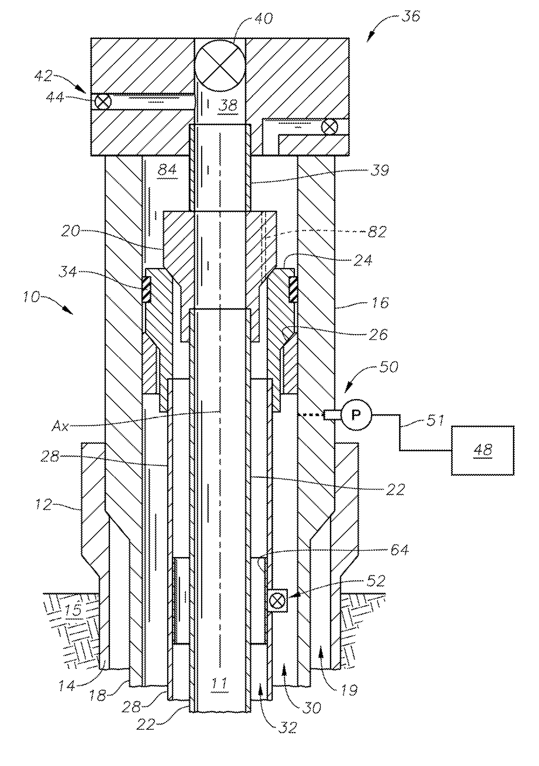
FIG. 1 provides a side partial cross-sectional view of an embodiment of a wellhead assembly 10 in accordance with the present disclosure. The wellhead assembly 10 can be used with a subsea well for controlling production fluid from within a hydrocarbon producing wellbore 11. An outer wellhead housing 12 is provided having an annular outer conductor pipe 14 extending from its bottom end into formation 15 intersected by the wellbore. Coaxially disposed within the outer wellhead housing 12 is a high pressure / inner wellhead housing 16. A string of surface casing 18 depends downward from the inner wellhead housing 16 and coaxial within the outer conductor pipe 14. An outer annulus 19 is formed between the outer conductor pipe 14 and surface casing 18.

The wellhead housing 16 coaxially circumscribes a tubing hanger 20 and production tubing 22 supported by the tubing hanger 20. A casing hanger 24 is also coaxially landed on a shoulder 26 within the wellhead housing 16. The shoulder 26 is fo...


PUM


Abstract

A wellbore tubular set concentrically between an inner an and outer annulus has a pressure relief valve that opens when pressure in the outer annulus exceeds pressure in the inner annulus by an amount that can damage the tubular. The relief valve closes and reseats when the pressure differential is reduced to below the damaging threshold. The relief valve can include a spring for reseating the valve. A pressure gauge can be included within the outer annulus for monitoring whether or not the relief valve is operating properly.

Description

1. FIELD OF THE INVENTIONThis invention relates in general to production of oil and gas wells, and in particular to an automated vent system that prevents overpressure within an annulus in a wellhead assembly.2. DESCRIPTION OF RELATED ARTSystems for producing oil and gas from subsea wellbores typically include a wellhead assembly that includes a wellhead housing attached at a wellbore opening, where the wellbore extends through one or more hydrocarbon producing formations. Casing and a tubing hanger are landed within the housing for supporting casing and production tubing inserted into the wellbore. The wellhead assembly may include strings of concentrically arranged casing, such as conductor pipe, surface casing, and an inner casing. Generally, the inner casing goes deeper than the conductor pipe and surface casing and lines the wellbore to isolate the wellbore from the surrounding formation. Tubing typically lies concentric within the inner casing and provides a conduit for produc...

Claims


Application Information

Patent Timeline
Patent Type & Authority Applications(United States)
IPC IPC(8): E21B34/02
CPCE21B34/08E21B33/03E21B34/02
Inventor FENTON, STEPHEN P.
Owner VETCO GRAY
Why Eureka
Try Eureka