Depressible key structure

Inactive Publication Date: 2011-05-19
PRIMAX ELECTRONICS LTD
View PDF11 Cites 10 Cited by
  • Summary
  • Abstract
  • Description
  • Claims
  • Application Information

AI Technical Summary

Benefits of technology

[0004]An object of the present invention provides a depressible key struct

Problems solved by technology

Since the key structure with the scissors-type support member has many pivotal parts, the upper fixing parts 75 and the lower fixing parts 76, the process of assembling the key structure is very troublesome.
In addition, since the components of the key structure are complicated and diversified, the fabricati

Method used


Image

  • Depressible key structure
  • Depressible key structure
  • Depressible key structure

Examples


first embodiment

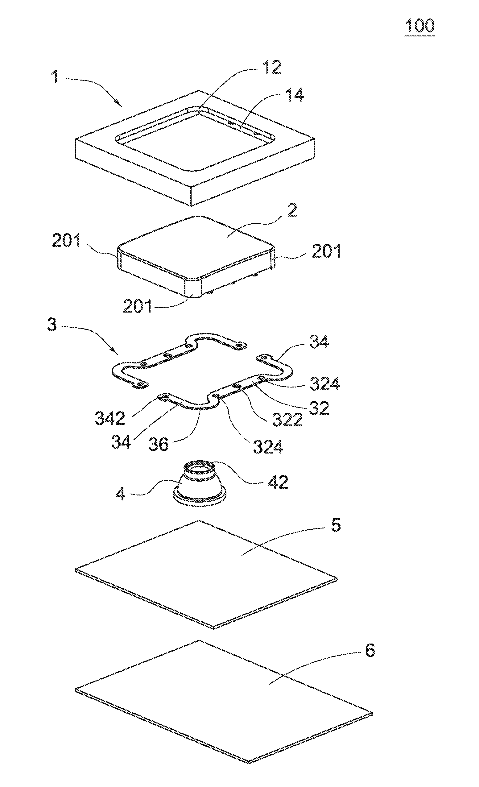
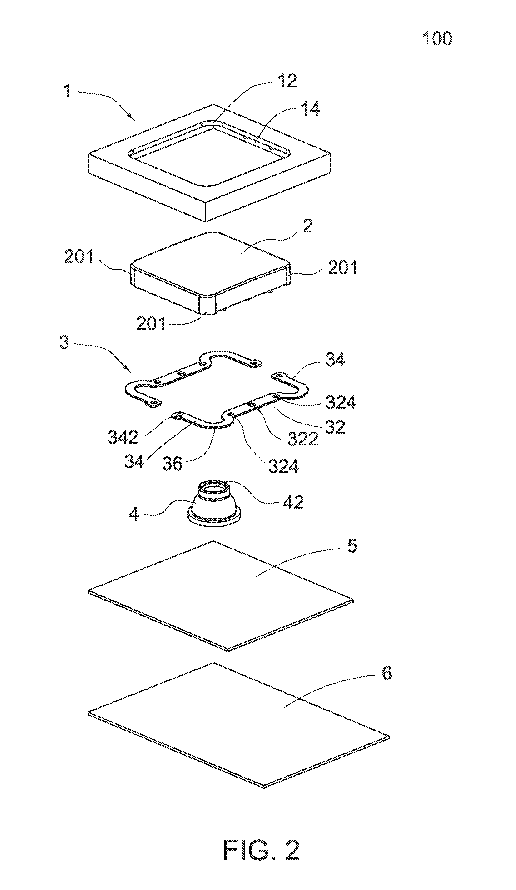
[0025]The depressible key structure of the present invention is not limited to be applied to a keyboard of a computer. For example, the depressible key structure is applied to a keyboard of a notebook computer. FIG. 2 is a schematic exploded view illustrating a depressible key structure according to the present invention. As shown in FIG. 2, the depressible key structure 100 comprises a key frame 1, a keycap 2, two elastic arms 3, an elastomeric element 4, a conductive membrane 5 and a base plate 6.

[0026]FIG. 6 is a schematic cutaway view illustrating an assembled depressible key structure that is not depressed according to the first embodiment of the present invention. Please refer to FIGS. 2 and 6. The key frame 1 is a square frame with a specified thickness. The key frame 1 has a central square receiving hole 12 running through the top and bottom surfaces thereof. The square receiving hole 12 may accommodate the keycap 2. In addition, a fret slot 14 not running through the top su...

second embodiment

[0035]FIG. 8 is a schematic view illustrating the elastic arms used in a depressible key structure according to the present invention. In this embodiment, the inner fixed arm part 32 is separated into the segments. Each elastic arm 3a includes an inner fixed arm part 32a, an outer movable arm part 34a perpendicular to the inner fixed arm part 32a, and a corner transition part 36a interconnected between the inner fixed arm part 32a and the outer movable arm part 34a. The inner fixed arm part 32a is positioned or fixed on a specified side of the bottom surface of the keycap 2. The corner transition part 36a is protruded out of the specified side to an adjacent side along a corresponding outer corner portion 201. In this embodiment, the number of the elastic arms 3a is equal to the number of the outer corner portions 201 of the keycap 2.


PUM


Abstract

A depressible key structure includes a key frame, a keycap, and plural elastic arms. The key frame has a receiving hole. The keycap is accommodated within the receiving hole, and includes plural outer corner portions. Each of the elastic arms includes an inner fixed arm part, at least one outer movable arm part, and a corner transition part interconnected between the inner fixed arm part and the at least one outer movable arm part. The corner transition parts of the elastic arms correspond to respective outer corner portions of the keycap. Each of the inner fixed arm parts is positioned at an inner edge of a specified side of a bottom surface of the keycap. A corresponding corner transition part is protruded out of the specified side to an adjacent side along a corresponding outer corner portion. The outer movable arm part is fixed on the key frame.

Description

FIELD OF THE INVENTION[0001]The present invention relates to a key structure, and more particularly to a flat depressible key structure.BACKGROUND OF THE INVENTION[0002]Recently, the general trends in designing computers and their peripheral devices are toward small size, light weightiness and easy portability. Take keyboards for example. The manufacturers of the keyboards are devoted to the study of designing slim keyboards in order to minimize the size thereof. In addition, the demands on enhancing comfort of the key structure and properly controlling the depressing force are gradually increased.[0003]Nowadays, the slim keyboard used in for example a notebook computer usually has a scissors-type support member for support the key structure. FIG. 1 is a schematic cross-sectional view illustrating a key structure with a scissors-type support member according to the prior art. As shown in FIG. 1, the key structure comprises a keycap 71, a rubbery elastomeric element 72, a scissors-ty...

Claims


Application Information

Patent Timeline
IPC IPC(8): H01H13/7065
CPCH01H3/122H01H13/705H01H2215/004H01H2231/042H01H2221/058H01H2227/036H01H2221/054
Inventor CHEN, BO-AN
Owner PRIMAX ELECTRONICS LTD
Why Eureka
Try Eureka