Liquid crystal display device and driving method thereof

a technology of liquid crystal display and display device, which is applied in the direction of instruments, static indicating devices, etc., can solve the problem of short time taken for the drive signal to exceed the threshold voltage, and achieve the effect of cost effectiveness

Inactive Publication Date: 2008-12-11
FUNAI ELECTRIC CO LTD
View PDF6 Cites 27 Cited by
  • Summary
  • Abstract
  • Description
  • Claims
  • Application Information

AI Technical Summary

Benefits of technology

[0020]The present invention discloses a liquid crystal display device capable of using a generally employed scan line drive method while providing the cost effectiveness, and the method for driving the liquid crystal display device.

Problems solved by technology

As a result, the time taken for the drive signal to exceed the threshold voltage becomes short.

Method used


Image

  • Liquid crystal display device and driving method thereof
  • Liquid crystal display device and driving method thereof
  • Liquid crystal display device and driving method thereof

Examples


Embodiment Construction

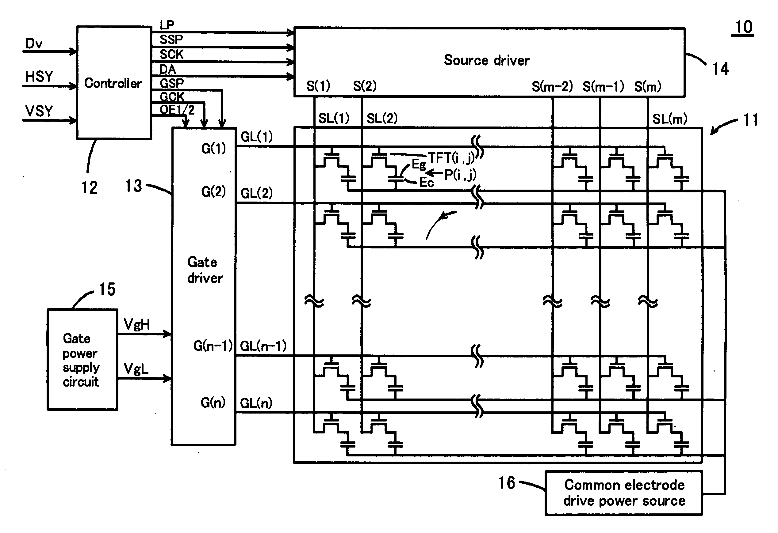
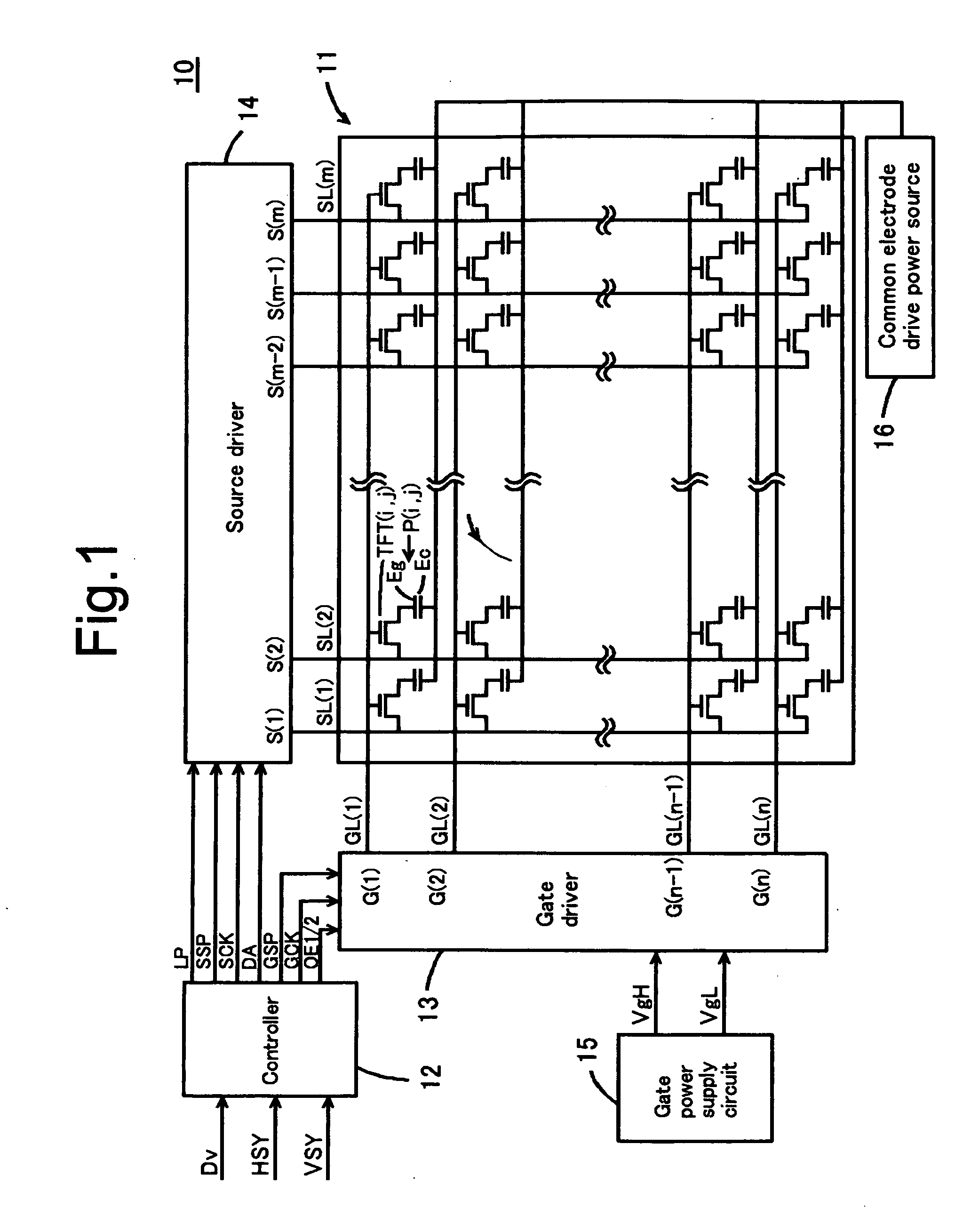
[0048]An embodiment of the present invention will be described in the following sections.[0049](1) Structure of liquid crystal display device:[0050](2) Function / Effect of liquid crystal display device:[0051](3) Modified examples:[0052](4) Outline:

(1) STRUCTURE OF LIQUID CRYSTAL DISPLAY DEVICE

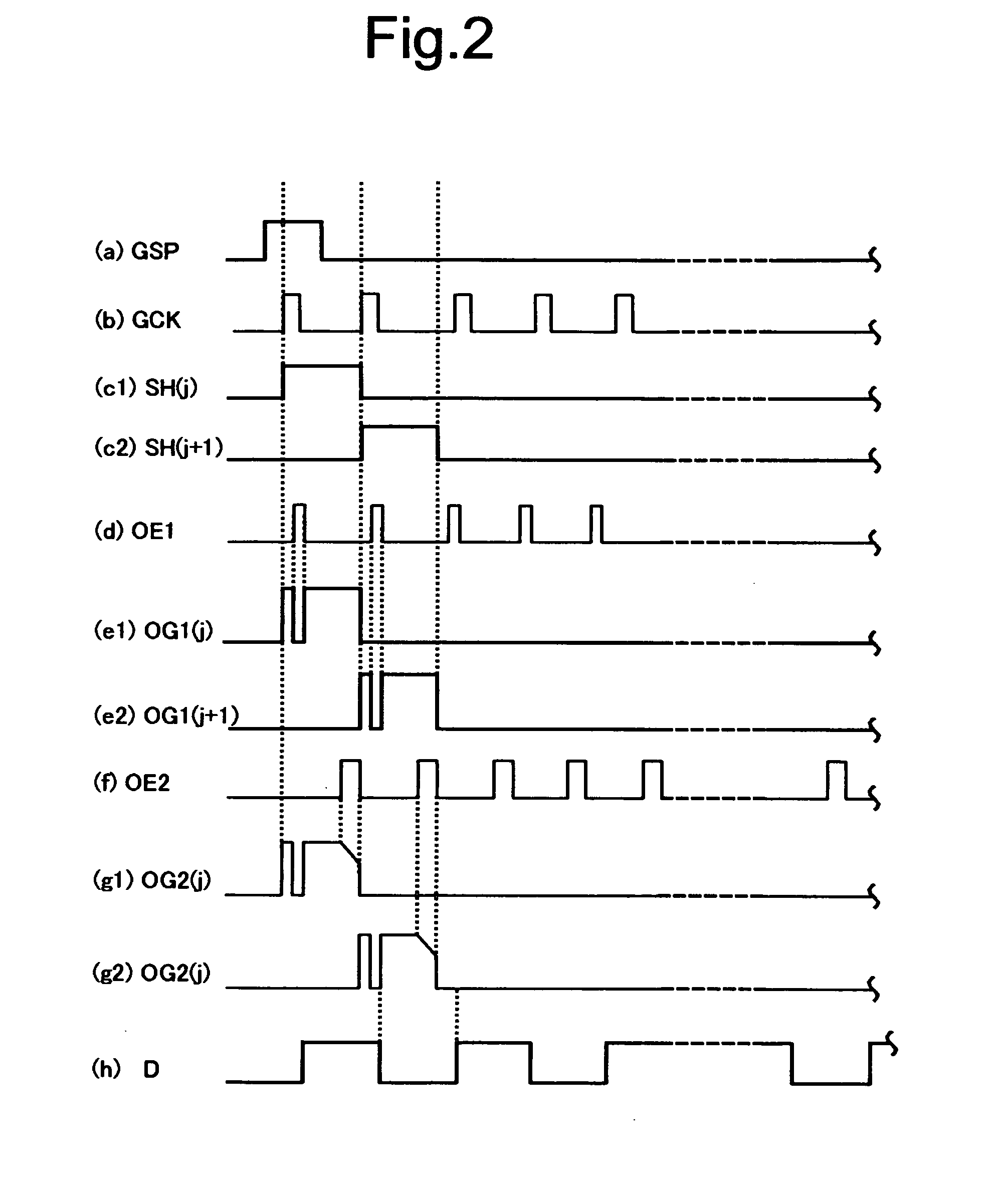
[0053]In a liquid crystal display device according to the invention, a TFT (switching element) is turned ON by a gate signal (drive signal) supplied from a gate driver (drive signal supply section) to supply a data signal from a source driver to pixels. The gate driver according to the present invention supplies the charge lower than the threshold voltage which turns the TFT ON before the charging period in the horizontal scan period to a gate electrode of the TFT, and the gate signal set as the voltage value higher than the threshold voltage in the charging period to the gate electrode of the TFT. The gate driver functions in sharpening the falling waveform gradient of the gate signal (as the ...


PUM


Abstract

In a liquid crystal display device, the TFT(i,j) is switched by a gate signal supplied from the gate driver 13 to supply the data signal to the pixels P(i,j). The gate driver 13 includes a charging waveform section with the electric charge lower than the threshold voltage to the TFT(i,j), a drive waveform section at the voltage higher than the threshold voltage, and a falling waveform section having the falling waveform modulated.

Description

CROSS-REFERENCES TO RELATED APPLICATIONS[0001]The present application is related to the Japanese Patent Application No. 2007-149024, filed Jun. 5, 2007, the entire disclosure of which is expressly incorporated by reference herein.BACKGROUND OF THE INVENTION[0002]1. Field of the Invention[0003]The present invention relates to a liquid crystal display device and a method of driving the liquid crystal display device.[0004]2. Description of the Related Art[0005]Generally, the liquid crystal display device displays the image using the liquid crystal having the molecule arrangement variable with the voltage. Japanese Unexamined Patent Application Publication No. 2006-133406 discloses the liquid crystal display device which includes a panel formed of pixels filled with the liquid crystal, the source driver which supplies the data signal to the panel, and the gate driver which specifies the pixel array for supplying the data signal in the horizontal scan period.[0006]In the aforementioned l...

Claims


Application Information

Patent Timeline
Patent Type & Authority Applications(United States)
IPC IPC(8): G09G3/36
CPCG09G3/3648G09G3/3677G09G3/3696G09G2310/065G09G2310/066G09G2310/08G09G2320/0223G09G2370/08
Inventor NAKATSUKA, HITOSHI
Owner FUNAI ELECTRIC CO LTD
Why Eureka
Try Eureka