Synthetic resin container closure

a technology of synthetic resin and container closure, applied in the direction of closure stoppers, caps, lids, etc., can solve the problems of broken breakable bridge portions and stress

a technology of synthetic resin and container closure, applied in the direction of closure stoppers, caps, lids, etc., can solve the problems of broken breakable bridge portions and stress

US20110114593A1Active Publication Date: 2011-05-19JAPAN CROWN CORK CO LTD

Image

  • Synthetic resin container closure
  • Synthetic resin container closure
  • Synthetic resin container closure

Examples


Embodiment Construction

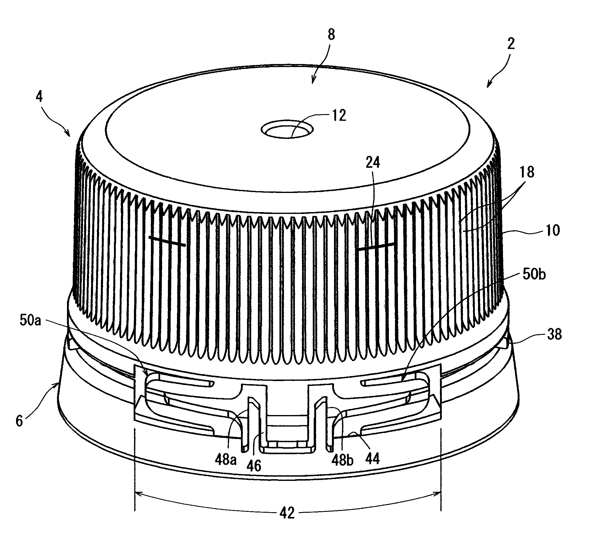
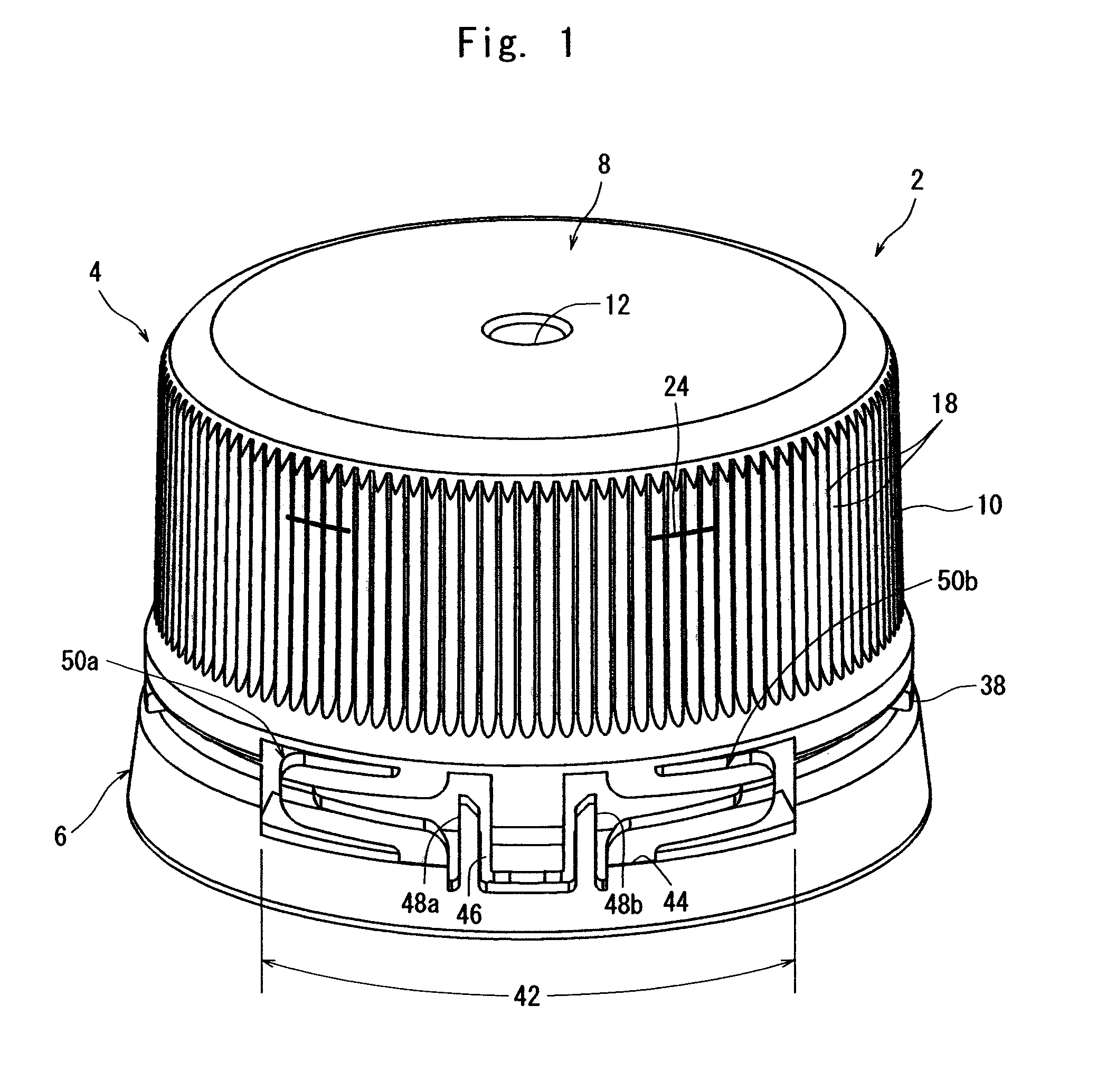
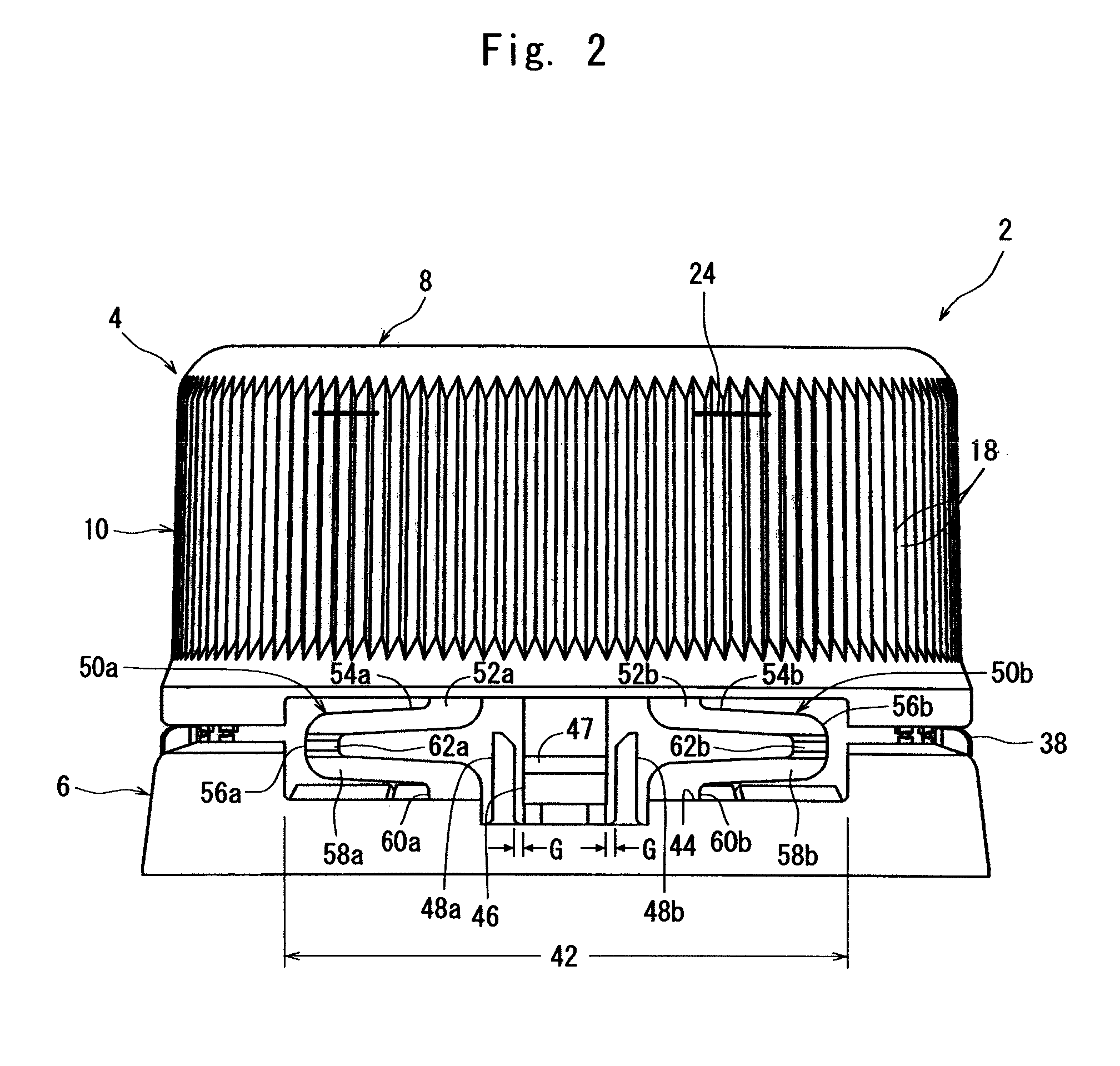
[0036]A preferred embodiment of a synthetic resin container closure constituted in accordance with the present invention will now be described in further detail with reference to the accompanying drawings.

[0037]With reference to FIGS. 1 to 3 showing the preferred embodiment of the synthetic resin container closure constituted in accordance with the present invention, the container closure designated entirely as the numeral 2 can be advantageously integral-molded from a suitable synthetic resin, such as polyethylene or polypropylene, by injection molding or compression molding. The container closure 2 includes a body 4 and a tamper evident bottom portion 6. The body 4 has a circular top panel wall 8, and a cylindrical skirt wall 10 extending downwardly from the peripheral edge of the top panel wall 8. A circular concavity 12 for avoiding the formation of a protrusion during injection molding is formed in the center of the upper surface of the top panel wall 8. Two sealing projections...


PUM


Abstract

[Problems to be Solved] In a synthetic resin container closure of a type which includes a body and a tamper evident bottom portion connected to the body via a plurality of breakable bridge portions arranged with spacing in a circumferential direction, and in which the body continues to be connected via unbroken connecting pieces to the tamper evident bottom portion continuously mounted on a mouth-and-neck portion of a container even after the bridge portions are broken to remove the body from the mouth-and-neck portion of the container, an improvement is made so that the container closure can be applied, without posing problems, even when the ascent distance of the body when removed is relatively long.[Means to Solve the Problems] Each of the unbroken connecting pieces is in such a form as to include two tilting portions whose tilting directions are opposite to each other.

Description

TECHNICAL FIELD[0001]This invention relates to a synthetic resin container closure having tamper evident properties of a type which is not separated, as a whole, from a container even after a mouth-and-neck portion of the container is unsealed. More particularly, the invention relates to a synthetic resin container closure of a type which includes a body and a tamper evident bottom portion connected to the body via a plurality of breakable bridge portions arranged with spacing in a circumferential direction, and in which the body continues to be connected via unbroken connecting pieces to the tamper evident bottom portion continuously mounted on the mouth-and-neck portion of the container even after the bridge portions are broken to release the body from the mouth-and-neck portion of the container.BACKGROUND ART[0002]A synthetic resin container closure having tamper evident properties is applied to a container which has an external thread formed on the outer peripheral surface of a ...

Claims


Application Information

Patent Timeline
19 May 2011
Publication
US20110114593A1
IPC
B65D41/32
CPC
B65D41/325; B65D55/16; B65D41/3428; B65D2251/1008; B65D2401/30; B65D41/34; B65D49/12
Inventors
ISHII, OSAMU; KIMURA, TAKASHI