
Touch panel device

Active Publication Date: 2011-05-19
SAMSUNG ELECTRONICS CO LTD
View PDF4 Cites 24 Cited by
  • Summary
  • Abstract
  • Description
  • Claims
  • Application Information

AI Technical Summary

Benefits of technology

[0018]An aspect of the present invention is to address at least the above problems and / or disadvantages and to provide at least the advantages described below. Accordingly, an aspect of the present invention is to provide a touch panel device in which a support portion is provided to include an actuator for generating vibration with an excellent sense of touch without the need for a separate mounting space, thereby improving both a sense of touch of a product and a haptic function.
[0019]Moreover, another aspect of the present invention is to provide a touch panel device in which an actuator for generating vibration with an excellent sense of touch is provided in a support portion opened forward without the need for a separate mounting space, thereby delivering the vibration of the actuator towards a front surface of a product and preventing the vibration from being delivered towards a rear surface of the product.
[0020]Furthermore, another aspect of the present invention is to provide a touch panel device in which an actuator for generating vibration with an excellent sense of touch is provided in a support portion opened forward to be coupled by insertion without the need for a separate mounting space, thereby achieving slimness and compactness of a product through reduction of the overall thickness of the product and improving the impact-resistance strength of the actuator.

Problems solved by technology

However, since simple touches of the transparent window of the portable communication device have proven to be unsatisfactory, users have demanded an interface which is more natural, easy to use and useful.
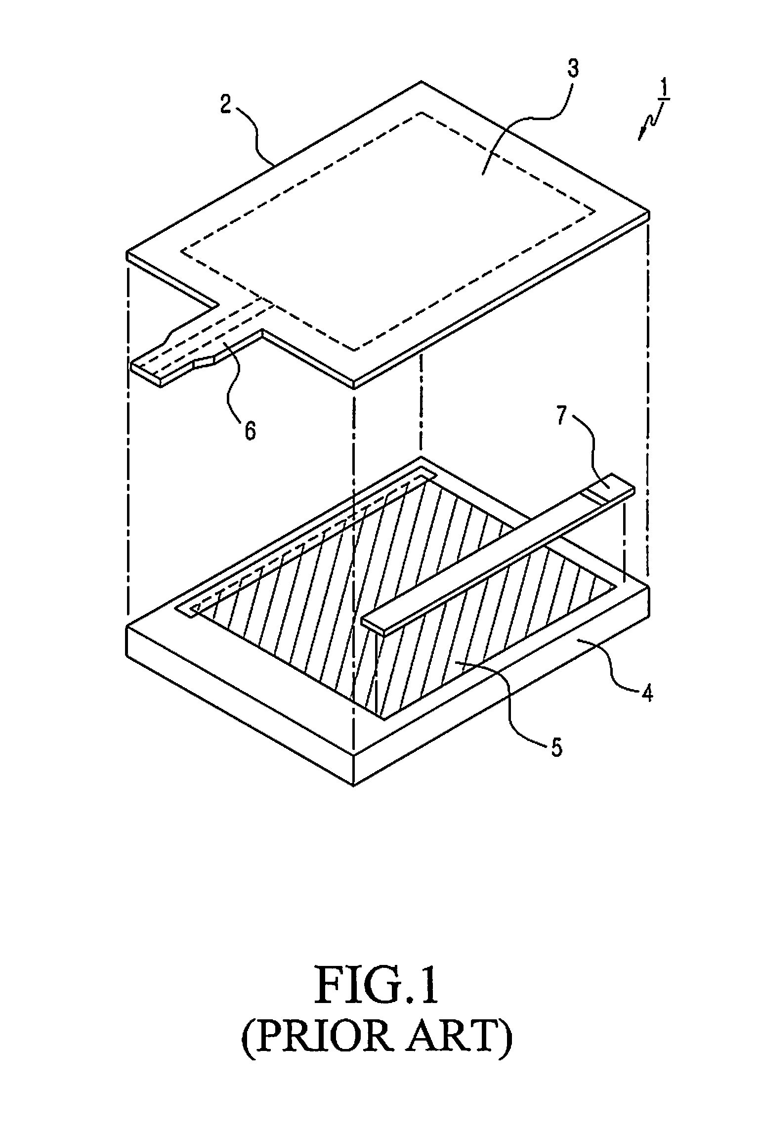
However, to mount the actuator providing the haptic function on the portable communication device using the conventional touch panel device, a separate space is required as shown in FIG. 1, and to this end, a spacer 7 has to be inserted between the touch sensor unit 3 and the display unit 5, increasing the overall thickness of the portable communication device and thus hindering slimness and compactness of the portable communication device.

Method used


Image

  • Touch panel device
  • Touch panel device
  • Touch panel device

Examples


first embodiment

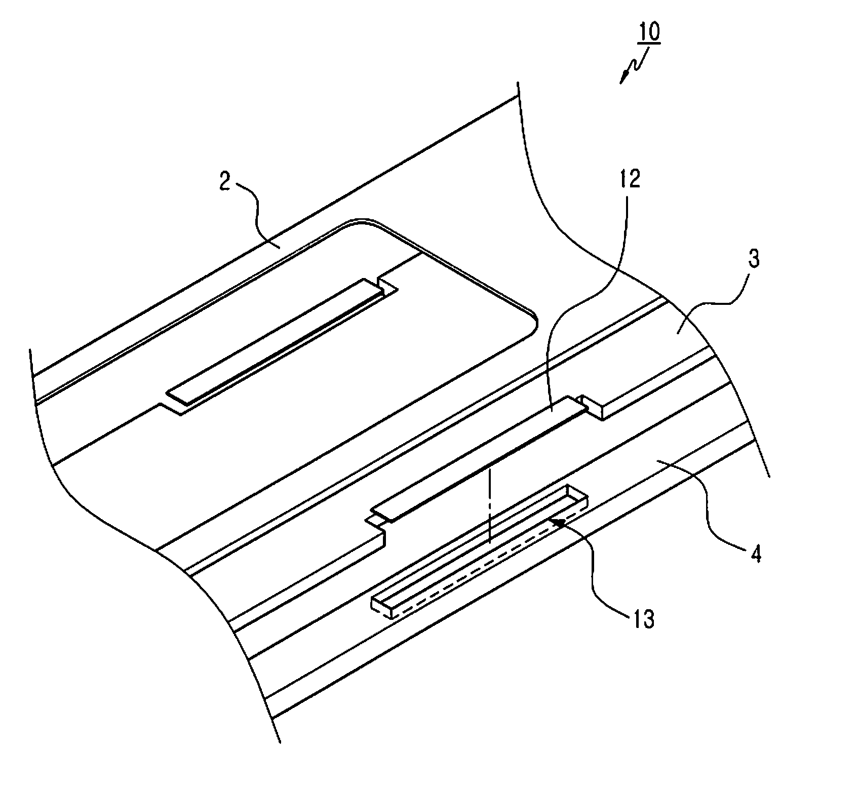
[0046]According to the present invention, the touch panel device 10 includes the front cover portion 2, the touch sensor unit 3 divided into the upper transparent electrode layer 3a and the lower transparent electrode layer 3b, the substrate 4 including the display unit (not shown), the actuator 11, the reinforcing portion 12, and the support portion 13. As shown in FIG. 4, the front cover portion 2 includes the window of the portable communication device (not shown), and the touch sensor unit 3 is attached onto a bottom surface of the window.

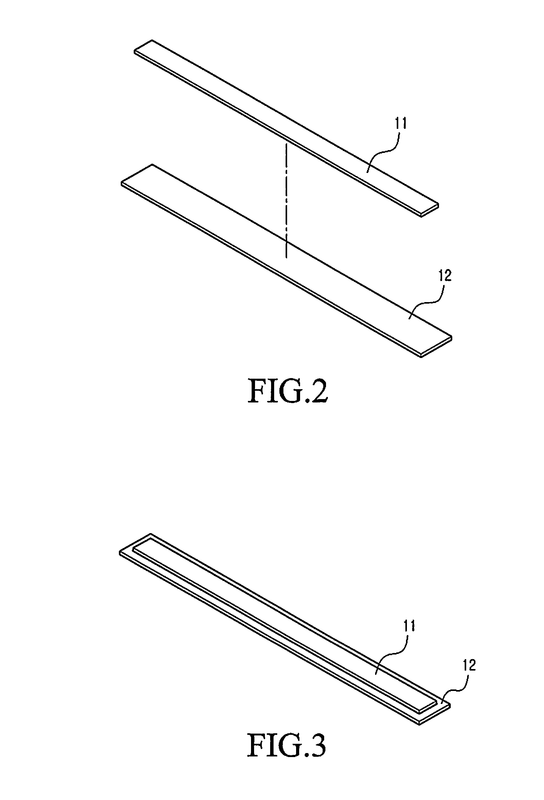
[0047]The actuator 11 is attached to the first surface of the reinforcing portion 12 by using the adhesive, the double-sided tape 14, or the like. In this state, the actuator 11 is inserted into and coupled to the support portion 13 formed in the substrate 4 and the lower transparent electrode layer 3b of the touch sensor unit 3 is attached to the second surface of the reinforcing portion 12. At the same time, as shown in FIG. 4, the window and...

second embodiment

[0051]With reference to FIGS. 9 through 14, according to the present invention, the touch panel device 20 includes the front cover portion 2, the touch sensor unit 3 divided into the upper transparent electrode layer 3a and the lower transparent electrode layer 3b, the substrate 4 including the display unit (not shown), an actuator 21, and a support portion 22.

[0052]The support portion 22 provides an opening 22c in a first side 22a thereof and a closed second side 22b. The actuator 21 is inserted into and coupled through the opening 22c. In this state, the support portion 22 is provided in the substrate 4 such that the support portion 22 supports the actuator 21 in such a way to deliver the vibration of the actuator 21 to the front cover portion 2 through the opening 22c.

[0053]As shown in FIGS. 10 through 14, the front cover portion 2 includes a window of the portable communication device (not shown), and the touch sensor unit 3 is attached to a bottom surface of the window, after ...


PUM


Abstract

A touch panel device in which a support portion is provided to include an actuator for generating vibration giving an excellent sense of touch without the need for a separate mounting space. To this end, the touch panel device having a front cover portion, a touch sensor unit divided into an upper transparent electrode layer and a lower transparent electrode layer, and a substrate provided under the touch sensor portion includes an actuator for delivering vibration to the front cover portion, a reinforcing portion having the actuator attached thereto to attach the actuator to the touch sensor unit, and a support portion formed on the substrate to provide an opening in a first side thereof and a closed second side, such that the actuator is inserted into and coupled to the opening and the support portion supports the actuator to deliver the vibration of the actuator to the front cover portion.

Description

PRIORITY[0001]This application claims priority under 35 U.S.C. §119(a) to a Korean Patent Application filed in the Korean Intellectual Property Office on Nov. 17, 2009 and assigned Serial No. 2009-110996, the entire disclosure of which is hereby incorporated by reference.BACKGROUND OF THE INVENTION[0002]1. Field of the Invention[0003]The present invention generally relates to a touch panel device, and in particular, to a touch panel device in which a support portion is provided to include an actuator for generating vibration giving an excellent sense of touch without the need for a separate mounting space.[0004]2. Description of the Related Art[0005]Generally, a touch panel device is a means for inputting information to a computer and is used together with various display forms including a cathode ray tube (CRT) and a Liquid Crystal Display (LCD). When disposed on a display unit, a touch panel device allows a user to select a displayed icon or element by triggering the user to touch...

Claims


Application Information

Patent Timeline
IPC IPC(8): H01L41/053
CPCG06F3/041G06F3/016G06F3/045G06F1/1643G06F3/0412G06F3/0414H10N30/20
Inventor LEE, HO-JIN
Owner SAMSUNG ELECTRONICS CO LTD
Learn More