Exhaust System of Motorcycle and Motorcycle Including Exhaust System

Inactive Publication Date: 2007-05-10
YAMAHA MOTOR CO LTD
View PDF8 Cites 6 Cited by
  • Summary
  • Abstract
  • Description
  • Claims
  • Application Information

AI Technical Summary

Benefits of technology

[0013] The invention solves the above problems and provides an exhaust system w

Problems solved by technology

While the front exhaust pipes sufficiently have the optimum length, the rear exhaust pipes have only a short length to reach the exhaust chamber and therefore cannot easily obtain the same length as that of the front exhaust pipes.
Location of such a heavy component at a rear posit

Method used


Image

  • Exhaust System of Motorcycle and Motorcycle Including Exhaust System
  • Exhaust System of Motorcycle and Motorcycle Including Exhaust System
  • Exhaust System of Motorcycle and Motorcycle Including Exhaust System

Examples


Example

[0027] An embodiment of the invention is now described with reference to the drawings. For simplification, similar reference numerals are given to components with substantially similar functions. The invention is not limited to the illustrated embodiments.

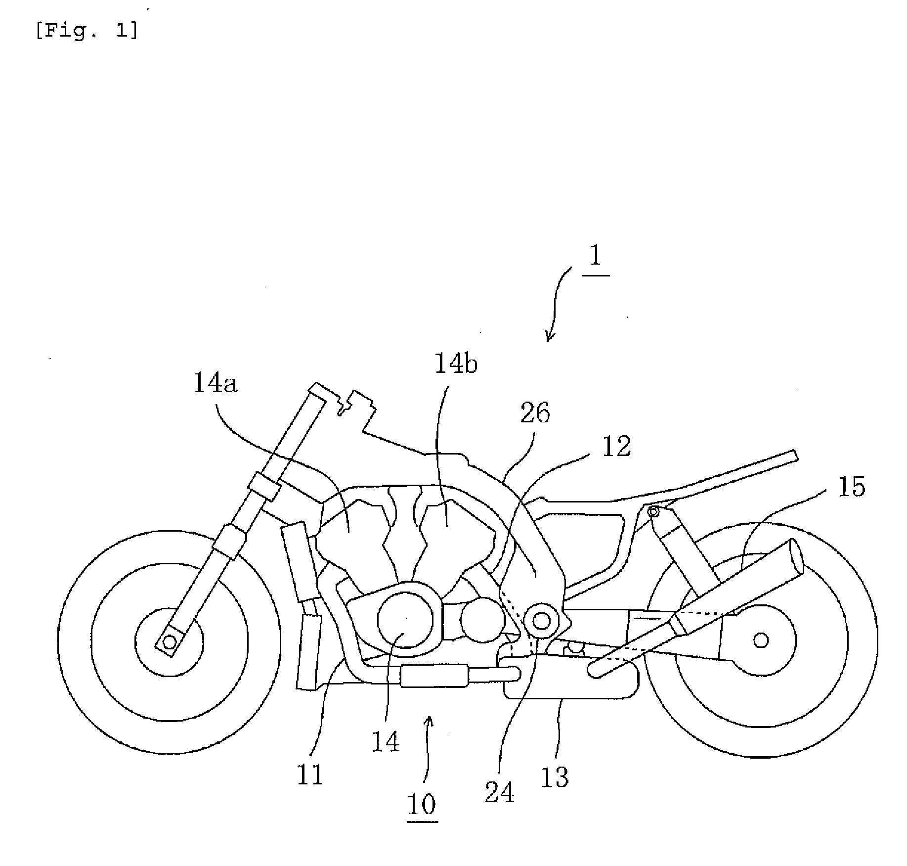
[0028]FIG. 1 illustrates a motorcycle 1 including an exhaust system 10 according to the invention.

[0029] As illustrated in FIG. 1, a V-type four-cylinder engine 14 is supported by a vehicle body frame 26. Front exhaust pipes 11 and rear exhaust pipes 12 extend to the rear of the vehicle body from, respectively, front cylinders 14a in front of engine 14 and rear cylinders 14b behind engine 14. Respective rear ends of front and rear exhaust pipes 11 and 12 are collectively joined to an exhaust chamber 13. An exhaust muffler 15 is connected with a rear part of exhaust chamber 13.

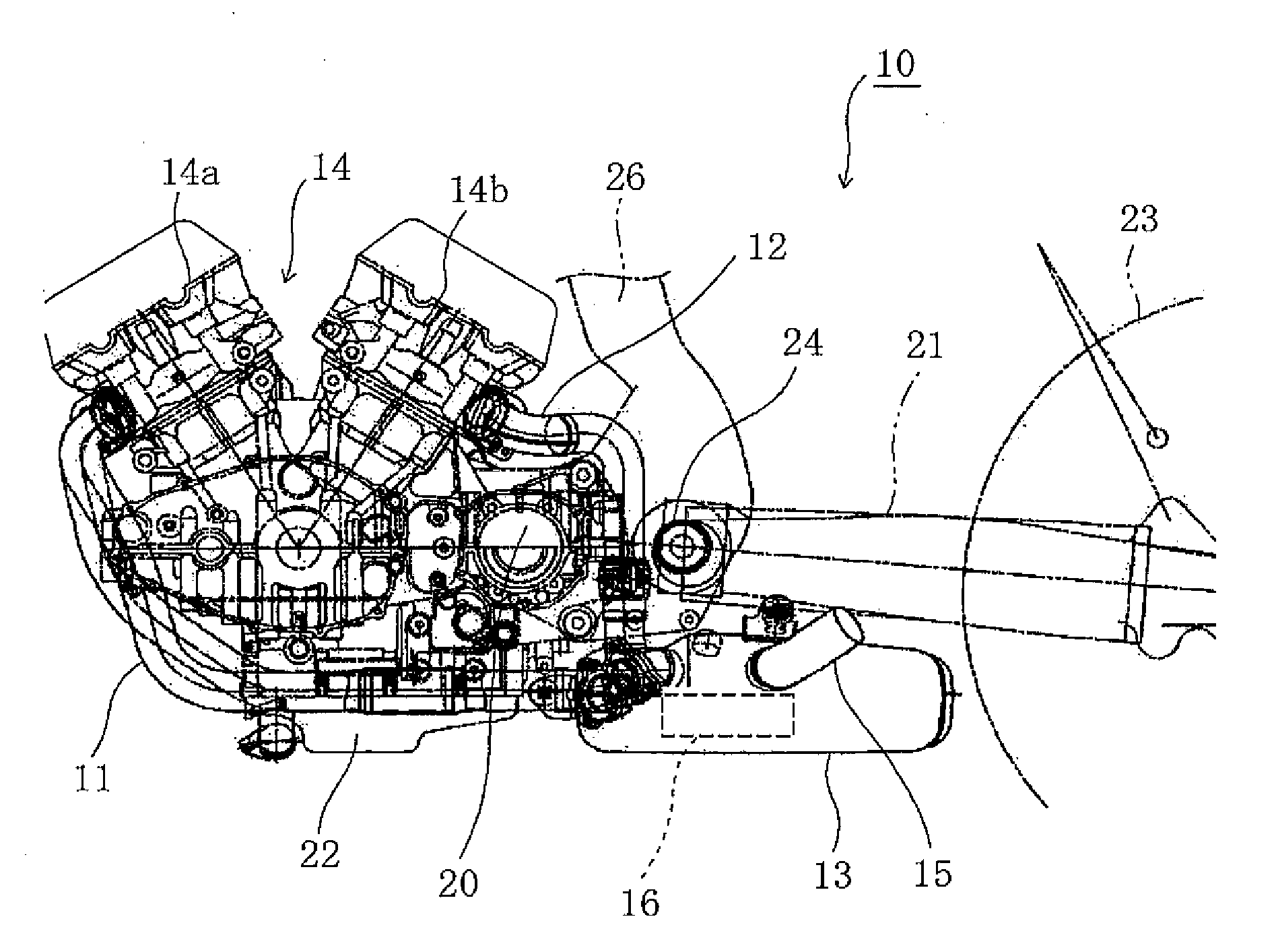
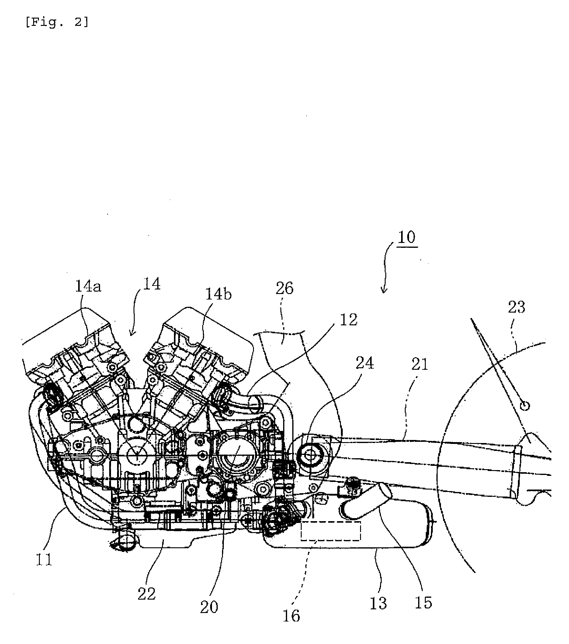
[0030] The basic structure of exhaust system 10 is described with reference to FIGS. 2 and 3.

[0031]FIGS. 2 and 3 are side and plan views of exhaust system...


PUM


Abstract

An exhaust system for a motorcycle provides enhanced steering stability and improved function for purifying exhaust gas. Front exhaust pipes connected with front cylinders of a V-type engine are joined to a front part of an exhaust chamber. Rear exhaust pipes connected with rear cylinders of the engine are joined to an upper part of the exhaust chamber. Exhaust gases discharged from both the front and rear exhaust pipes are unified within the exhaust chamber, and a catalyst is disposed in the vicinity of the unifying section. The length of the rear exhaust pipes is shorter than the length of the front exhaust pipes. High-temperature exhaust gas is introduced to the catalyst contained within the exhaust chamber via the rear exhaust pipes.

Description

RELATED APPLICATIONS [0001] This application claims the benefit of priority under 35 USC 119 of Japanese patent application no. 2005-294629, filed on Oct. 7, 2005, which application is hereby incorporated by reference in its entirety. BACKGROUND OF THE INVENTION [0002] 1. Field of the Invention [0003] The present invention relates to an exhaust system of a motorcycle, and more particularly to an exhaust system of a motorcycle which has a V-type engine and an exhaust gas purifying function. [0004] 2. Description of Related Art [0005] In a typical exhaust system of a motorcycle with a V-type engine, front exhaust pipes connected with cylinders disposed in front of an engine and rear exhaust pipes connected with cylinders disposed behind the engine are joined to an exhaust muffler via an exhaust chamber. [0006] In this layout, the front and rear exhaust pipes preferably have an optimum length to secure appropriate function of the engine. While the front exhaust pipes sufficiently have ...

Claims


Application Information

Patent Timeline
IPC IPC(8): B60K13/04B62M7/02F01N3/24F01N13/08
CPCF01N3/10F01N13/08F01N2340/04F01N2470/14F01N2470/16F01N2590/04F01N13/011Y02A50/20
Inventor HARADA, KEIICHI
Owner YAMAHA MOTOR CO LTD
Why Eureka
Try Eureka