Rotational angle measurement apparatus

a measurement apparatus and rotational angle technology, applied in the direction of instruments, galvano-magnetic devices, magnetic field measurement using galvano-magnetic devices, etc., can solve problems such as errors in measured angles

Active Publication Date: 2011-05-19
HITACHI LTD
View PDF6 Cites 21 Cited by
  • Summary
  • Abstract
  • Description
  • Claims
  • Application Information

AI Technical Summary

Benefits of technology

[0043]The present invention intends to provide a rotational angle measurement apparatus capable of correcting an error caused by a pin-angle error with a small amount of calculation operation.

Problems solved by technology

As described above, the magnetic field measurement apparatus using the magneto-resistance element having the pinned magnetic layer involves a problem that error occurs in the measured angle when there is a setting error for the magnetization direction of the pinned magnetic layer (pin angle).

Method used


Image

  • Rotational angle measurement apparatus
  • Rotational angle measurement apparatus
  • Rotational angle measurement apparatus

Examples


first embodiment

[0092]The constitution and the operation of a rotational angle measurement apparatus according to the invention are to be described with reference to FIGS. 5 to 7.

[0093]First of all, a first constitution of the rotational angle measurement apparatus for examining a pin-angle error a according to this embodiment is to be described with reference to FIG. 5.

[0094]Following abbreviations are used in FIGS. 5, 8, 11, 13, 19, 20, 23, 24, and 25: “ROT. AGL. MEA. APPR” stands for “rotational angle measurement apparatus”; “MAG.SENS” stands for “magnetic sensor”; “DETC.CKT” stands for “detection circuit unit”; “SIG.PROC” stands for “signal processing unit”; “AVR.” stands for “averaging unit”; “DUR.DETM” stands for “duration-determination unit”; “MEM” stands for “parameter-storing unit”.

[0095]FIG. 5 is a block diagram showing the first constitution of the rotational angle measurement apparatus for examining the pin-angle error α according to the first embodiment of the invention.

[0096]A rotatio...

second embodiment

[0143]The constitution and the operation of a rotational angle measurement apparatus according to the invention are to be described with reference to FIGS. 8 to 10.

[0144]First, a first constitution of the rotational angle measurement apparatus for correcting the pin-angle error α according to this embodiment is to be described with reference to FIG. 8.

[0145]FIG. 8 is a block diagram showing the first constitution of the rotational angle measurement apparatus for correcting the pin-angle error α according to the second embodiment of the invention.

[0146]FIG. 8 shows a circuit constitution for executing correction processing during operation as a rotational angle sensor in which a rotational angle measurement value is corrected by using the sine β (=sin α) of the error α determined by the constitution of FIG. 5.

[0147]A rotational angle measurement apparatus 201M of this embodiment includes a magnetic sensor 301 and a detection circuit unit 302M. The detection circuit unit 302M has a si...

third embodiment

[0173]Then, description is to be made to a first constitution of a rotational angle measurement apparatus for examining a pin-angle error α and correcting the pin-angle error α according to the invention with reference to FIG. 11.

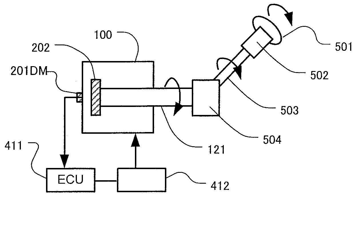
[0174]FIG. 11 is a block diagram showing the first constitution of the rotational angle measurement apparatus for examining the pin-angle error α and correcting the pin-angle error α according to the third embodiment of the invention. In FIG. 11, identical reference numerals to those of FIGS. 5 and 8 denote identical portions.

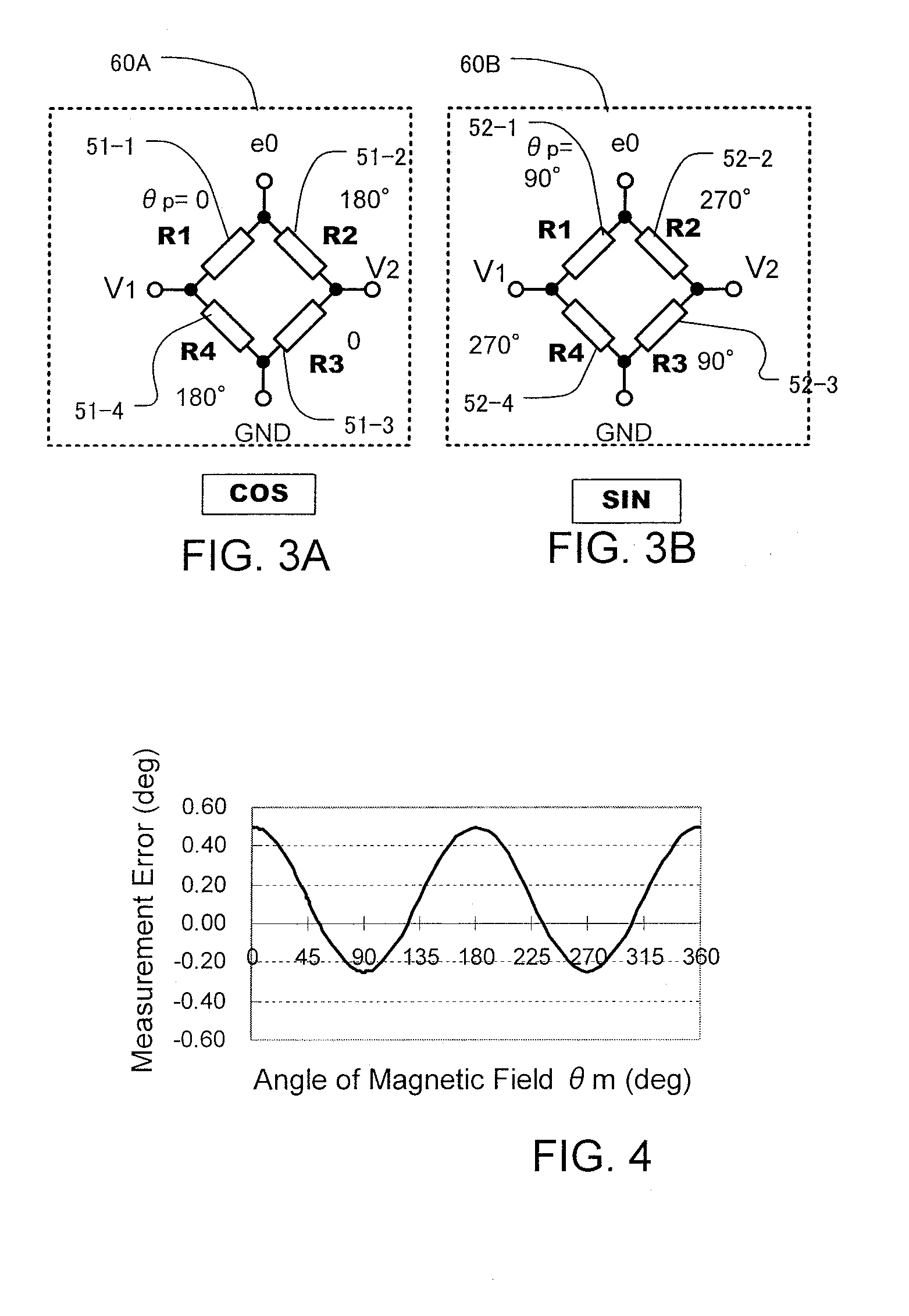
[0175]A rotational angle measurement apparatus 201DM of this embodiment includes a magnetic sensor 301 and a detection circuit unit 302DM. The detection circuit unit 302DM has a signal processing unit 303DM. The magnetic sensor 301 has two bridges (COS bridge and SIN bridge) each comprising GMR elements. A differential amplifier 351A detects a difference voltage between terminals V1 and V2 of the COS bridge and outputs a difference sig...


PUM


Abstract

The object of the invention is to provide a rotational angle measurement apparatus that is capable of correcting an error due to pin-angle error with a small amount of calculation operation.The rotational angle measurement apparatus includes a magnetic sensor 301 and a signal processing unit 303M. The magnetic sensor includes two bridges comprising magneto-resistance elements each having a pinned magnetic layer. A ratio-calculation unit 381 of the signal processing unit 303M calculates a ratio Vy / Vx of output signals Vx and Vy. A parameter correction unit 382 subtracts a predetermined correction parameter β from the ratio Vy / Vx calculated by the ratio-calculation unit. An a tan-processing unit 383 conducts arctangent processing on the value calculated by the parameter correction unit and calculates an angle of magnetic field θ.

Description

BACKGROUND OF THE INVENTION[0001]1. Field of the Invention[0002]The present invention relates to a rotational angle measurement apparatus including a magneto-resistance element (MR element) having a pinned magnetic layer. The invention particularly relates to a rotational angle measurement apparatus capable of correcting a pin-angle error.[0003]2. Description of the Related Art[0004]A rotational angle measurement apparatus using such an MR element is known, for example, by Japanese Patent No. 3799270, etc.[0005]Examples of known magneto-resistance elements (MR element) include a giant magneto-resistance element (GMR element) and a tunneling magneto-resistance element (TMR element). The outline of MR element is to be described by way of a magnetic field measurement apparatus using a GMR element as an example.[0006]FIG. 1 shows a basic structure of the GMR element.[0007]The GMR element has a first magnetic layer 13 (pinned magnetic layer) and a second magnetic layer 11 (free magnetic ...

Claims


Application Information

Patent Timeline
Patent Type & Authority Applications(United States)
IPC IPC(8): G01B7/30
CPCG01D5/145
Inventor SUZUKI, MUTSUMI
Owner HITACHI LTD
Why Eureka
Try Eureka