Economical partially collimating reflective micro optical array

a micro-optical array and reflective technology, applied in the direction of discharge tube luminescnet screens, semiconductor devices for light sources, lighting and heating apparatus, etc., can solve the problems of non-uniform polymerization at the target, reducing the irradiance of the plurality, and falling to a level that is not sufficient to achieve the desired degree of polymerization

Inactive Publication Date: 2011-05-19
SILICON VALLEY BANK
View PDF32 Cites 41 Cited by
  • Summary
  • Abstract
  • Description
  • Claims
  • Application Information

AI Technical Summary

Problems solved by technology

However, at this distance, the irradiance falls to a level that is not sufficient to achieve the desired degree of polymerization.
The challenge is to increase the irradiance at the target distance without increasing the variation in the irradiance pattern at the work surface to a level that causes non-uniform polymerization at the target.
There are some problems with this design when applied to the field of UV Curing.
The size of the optic severely limits the number of modules that can be placed in one square centimeter which significantly reduces the irradiance that the plurality of modules can deliver to a work surface.
The second problem is that the design substantially collimates the light emitted from the module.
When a

Method used


Image

  • Economical partially collimating reflective micro optical array
  • Economical partially collimating reflective micro optical array
  • Economical partially collimating reflective micro optical array

Examples


Embodiment Construction

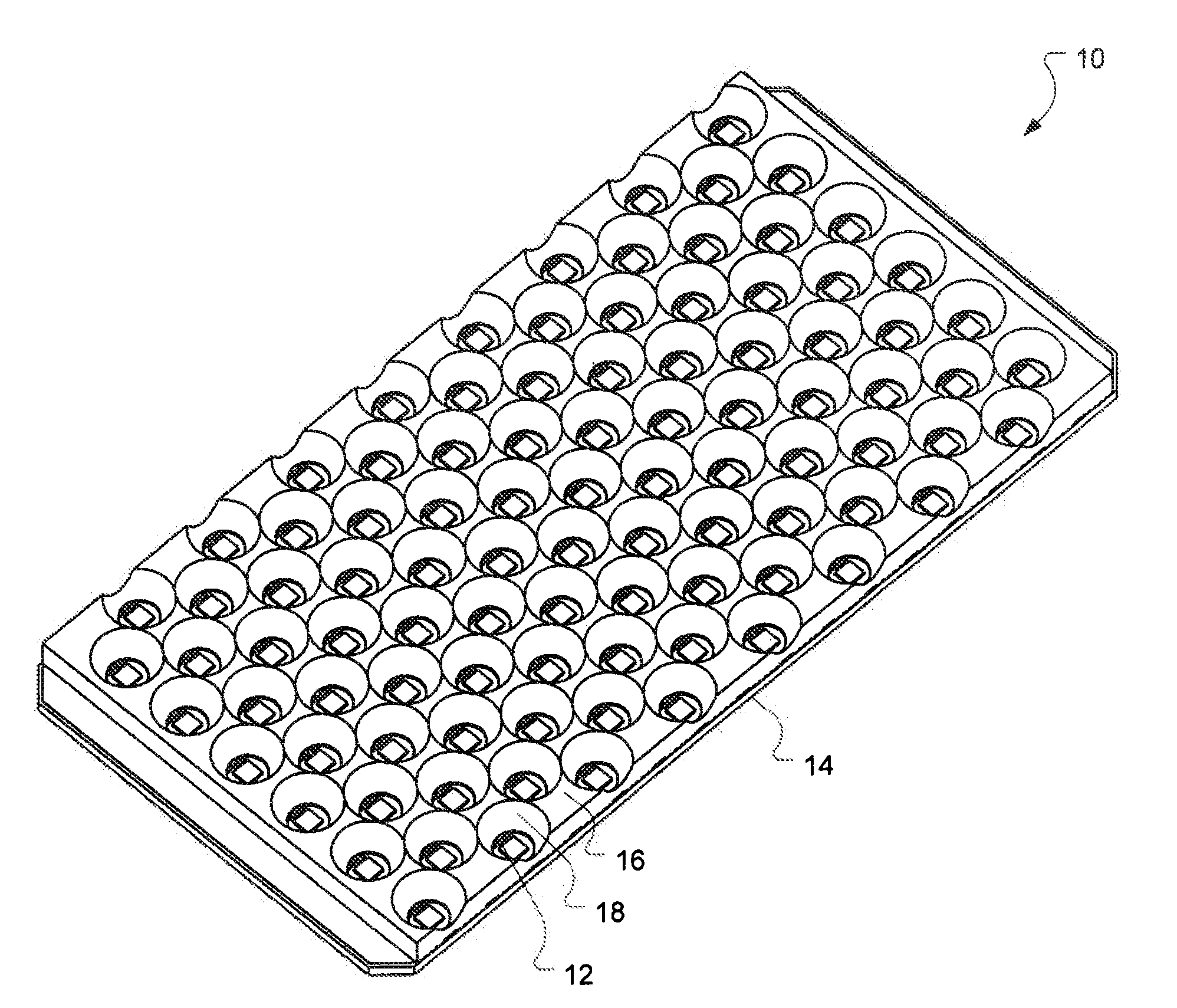
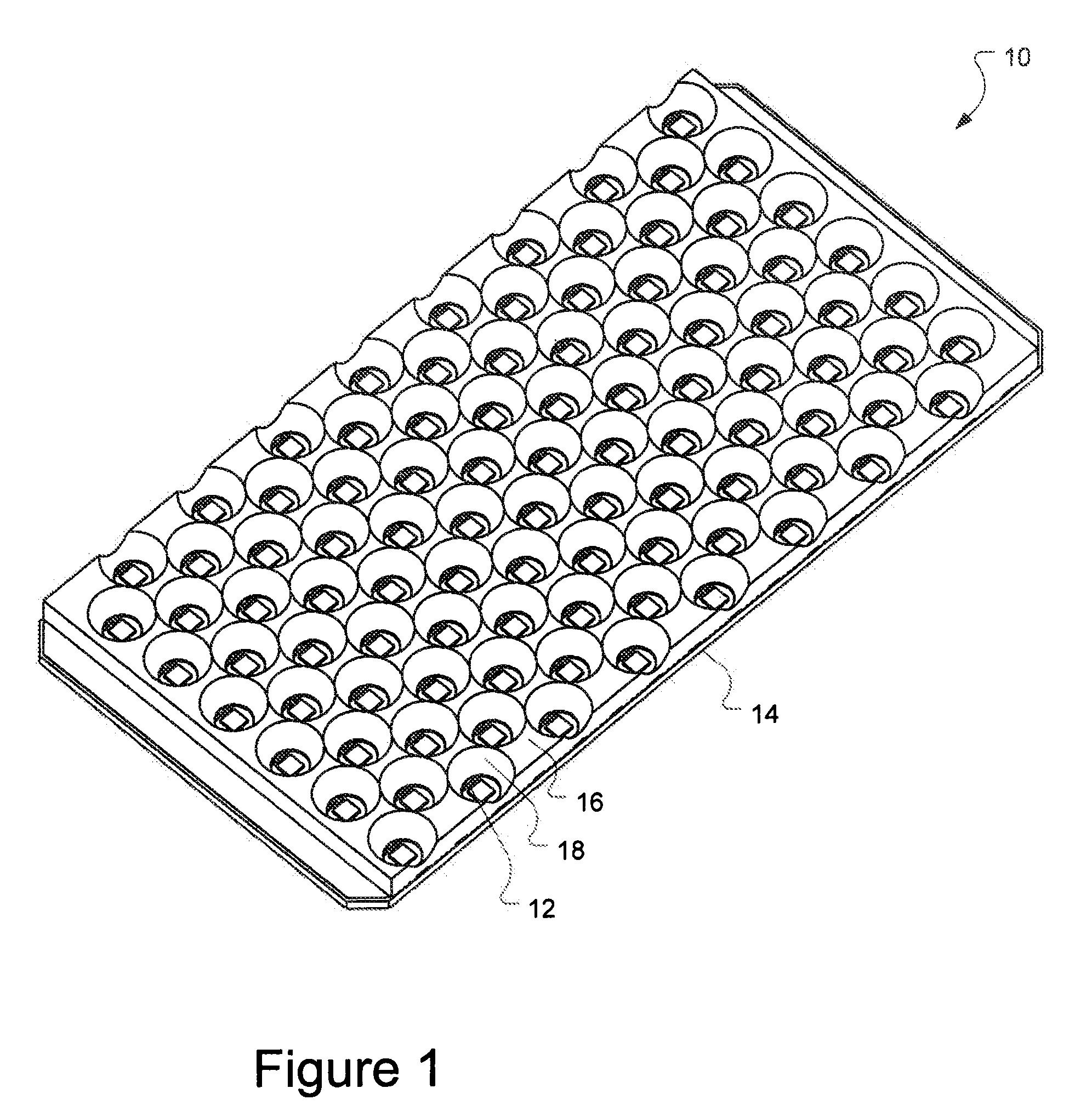
FIG. 1 shows a perspective view of a lighting module 10. The lighting module 10 includes a substrate 14 upon which individual light emitting elements 12 are arranged in an x-y grid. Examples of individual light emitting elements include light emitting diodes, including organic light emitting diodes (OLEDs). Generally, these light emitting elements are arranged on the substrate with the appropriate lines to provide power and control of the elements.

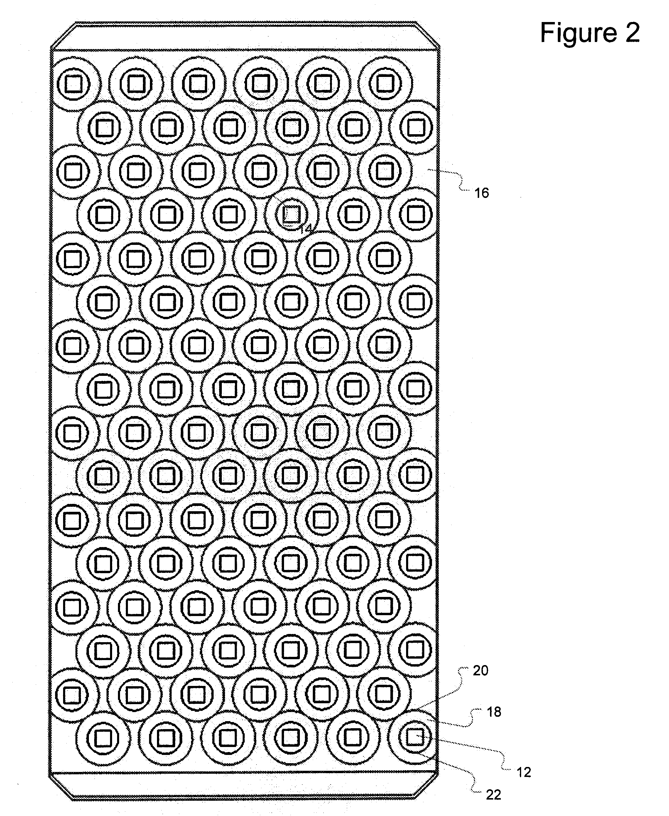
A reflector plate 16 is then attached to the substrate 14. The reflector plate 16 is a material which has an array of openings such as 18 that act as reflector cups for each light emitting element 12. The array of openings is arranged so that there is one opening for each light emitting element. Generally, the reflector plate is manufactured so the light emitting elements are centered in each opening and the shape of the opening is controlled to achieve the desired modification to the emission pattern of light from the light emitting eleme...


PUM


Abstract

A lighting module has an array of light emitting elements arranged on a substrate in an x-y grid, and a reflector plate arranged on the substrate, the reflector plate having an array of openings arranged on an x-y grid such that the openings correspond to the light emitting elements, the dimensions of the reflector plate and the openings arranged to partially collimate light from the light emitting elements. A method of manufacturing a lighting module includes arranging an array of light emitting elements on a substrate, manufacturing a reflector plate having an array of openings, the openings located so as to correspond to the light emitting elements and created so as to only partially collimate light from the light emitting elements, and attaching the reflector plate to the substrate such that each opening in the reflector plate is centered on a light emitting element.

Description

BACKGROUNDUltraviolet (UV) curing has many applications in printing, coating and sterilization. UV-sensitive materials generally rely upon a particular amount of energy in the form of UV light to initiate and sustain the curing process (polymerization) within the materials. UV light fixtures, commonly known as UV lamps, provide the UV light to the materials for curing.Using arrays of light emitting diodes (LEDs) in UV curing has several advantages over using arc lamps, including lower power consumption, lower cost, cooler operating temperatures, etc. Generally, the arrays consist of individual LED elements arranged in an X-Y grid on a substrate. The goal of the array is to deliver UV light to a target work surface at a given distance from the array with high irradiance and low variation in irradiance throughout the illuminated area at the work surface. The LEDs are diffuse point sources, which leads to uniform illumination at a given distance. However, at this distance, the irradian...

Claims


Application Information

Patent Timeline
IPC IPC(8): F21V7/00B29D11/00
CPCB29D11/00278B29D11/00596F21V7/0083H01L33/60F21Y2105/001H01L25/0753F21Y2101/02H01L2924/0002H01L2924/00F21Y2115/10F21Y2105/10
Inventor MARSON, JONATHAN L.
Owner SILICON VALLEY BANK
Why Eureka
Try Eureka