
Device And Method For The Automated Decontamination Of A Nuclear Fuel Rod

a technology of nuclear fuel rods and devices, which is applied in the field of nuclear fuel rod manufacturing, can solve the problems of electrode discharge, difficult and expensive processing, and high implementation cos

Inactive Publication Date: 2011-05-19
AREVA NC
View PDF10 Cites 0 Cited by
  • Summary
  • Abstract
  • Description
  • Claims
  • Application Information

AI Technical Summary

Benefits of technology

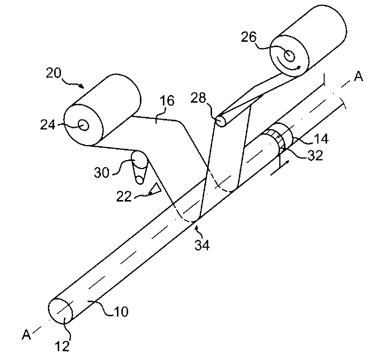
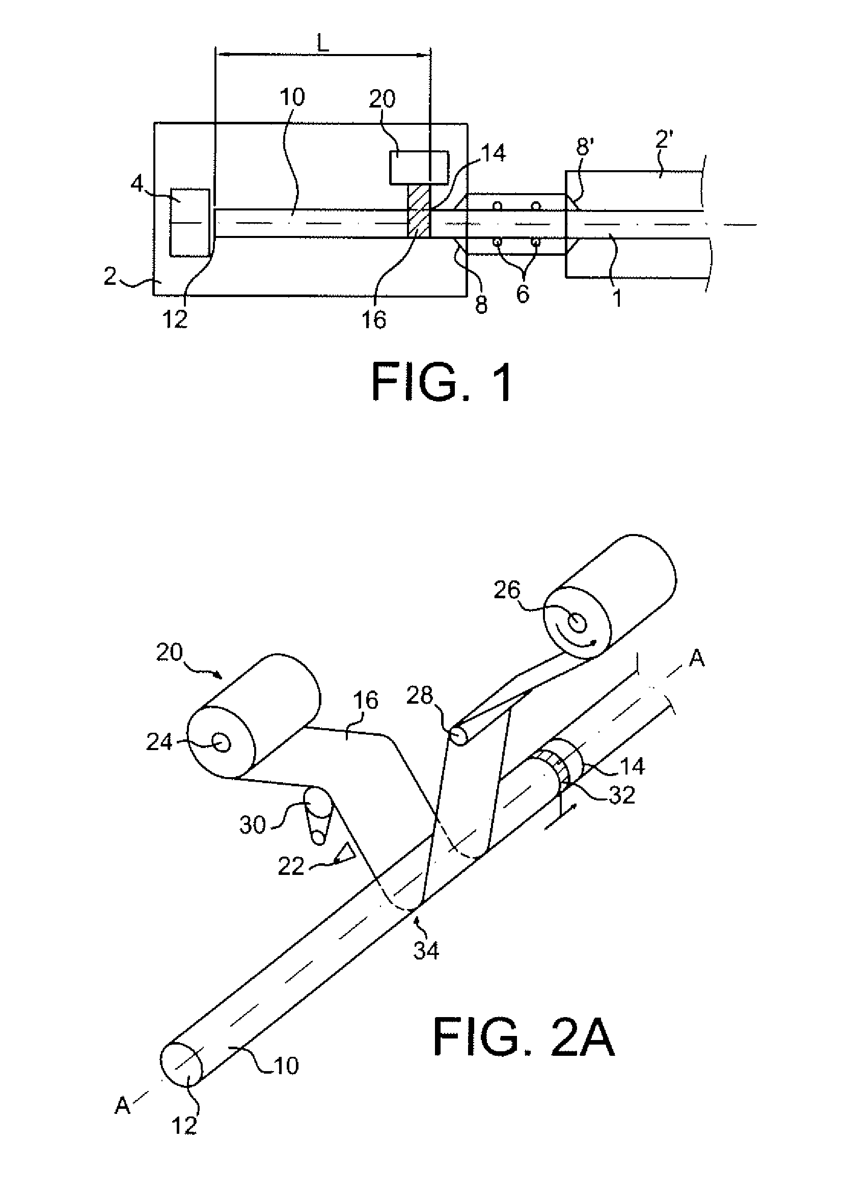
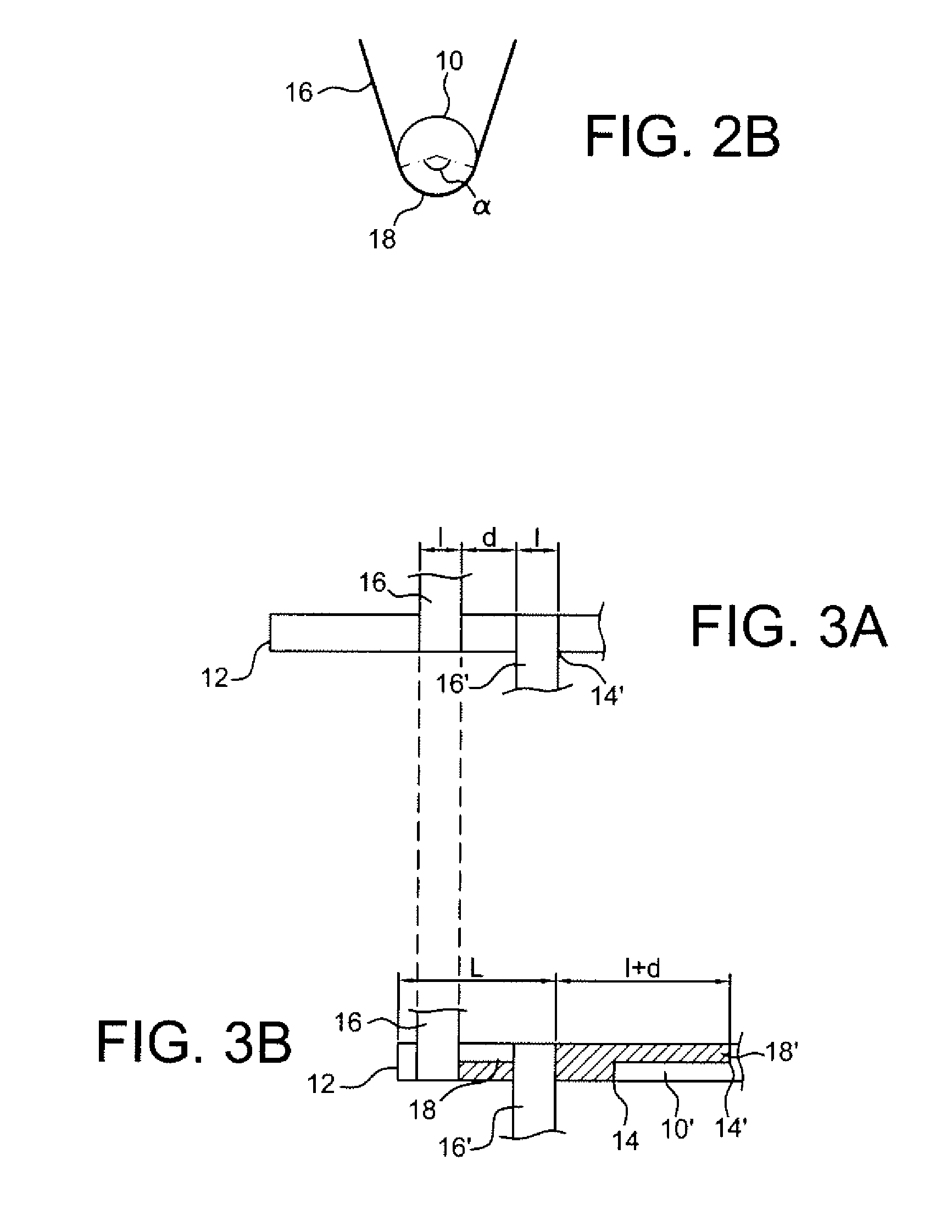
[0014]The decontamination method according to the invention comprises the placing of the length of cylinder to be decontaminated at a predetermined position, the tensioning of the band around the cylinder and the movement of the band in a direction perpendicular to the axis of the cylinder. During the cleaning by a method according to the invention, the tension of the band remains constant; the length of cylinder can be kept fixed or it may undergo a translation along it axis, at a constant speed of movement or comprising stages of slowing down in order to focus on a portion of the length; this translation may be accompanied by a slight rotation, so that the cylinder is driving in a helical movement, but it is preferable for the length to be kept in the same angular position throughout the process.

Problems solved by technology

For example, pressurised gas or solution jets (EP 0 100 428) may make it possible to remove the deposit of submicron particles of fuel, but give rise to effluents that it is difficult and expensive to process.
Other systems, comprising for example electrode discharges (GB 1 382 915), are very expensive to implement; laser decontamination (FR 2 774 801) has been envisaged, but remains very complex to use.
This solution is however limited geographically to the end of the rod and has not demonstrated its effectiveness in the light of the lack of reliability and the pressure exerted between band and rod.

Method used


Image

  • Device And Method For The Automated Decontamination Of A Nuclear Fuel Rod
  • Device And Method For The Automated Decontamination Of A Nuclear Fuel Rod
  • Device And Method For The Automated Decontamination Of A Nuclear Fuel Rod

Examples


Embodiment Construction

[0027]The total radioactive contamination of a sample, such as a fuel rod, consists of a so-called labile, or transferable, contamination resulting from a surface deposition of particles, and possibly a fixed contamination; the standard criteria for a rod are total residual contamination of less than 0.8 Bq / cm2 and a labile residual contamination of less than 4.10−2 Bq / cm2.

[0028]The method according to the invention acts mainly on labile contamination; however, by the injection of liquid in particular, an elimination of embedded particles may also be obtained.

[0029]The manufacture of the rods 1 is carried in a glove box system illustrated in FIG. 1. The glove boxes thus form functional sealed modules 2, 2′ in which the rods 1, with a normal diameter of approximately 9.5 to 12.5 mm, for a length of around 4 m, are at least partially inserted, in order to come to be connected with accessories 4 such as plugs or sheathing nose facilitating the operations, by movement by adapted mechani...


PUM


Abstract

A method for the surface tribological decontamination of nuclear fuel rods automates surface wiping by one or more bands of fabric. The band is distant from the axis of the rod, the rod is placed facing the band, and then the band is tensioned around the surface of the rod and moved. The rod may be immobile, moved in pure translation along its axis or with a wide-step helical movement. Preferably, the decontamination is carried by two bands simultaneously, so as to cover the total surface in one pass of the rod.

Description

CROSS REFERENCE TO RELATED APPLICATIONS OR PRIORITY CLAIM[0001]This application is a national phase of International Application No. PCT / EP2006 / 069428, entitled “DEVICE AND METHOD FOR THE AUTOMATED DECONTAMINATION OF A NUCLEAR FUEL ROD”, which was filed on Dec. 7, 2006, and which claims priority of French Patent Application No. 05 53810, filed Dec. 9, 2005.DESCRIPTION[0002]1. Technical Field[0003]The invention concerns the manufacture of nuclear fuel rods and in particular the surface cleaning and decontamination thereof.[0004]The invention relates in particular to a novel automated method for eliminating any deposits of residues by the use of one or more bands sliding along the surface of a cylindrical object. Another object of the invention is an adapted device.[0005]2. Prior Art[0006]A nuclear fuel rod for a water reactor consists of fuel pellets with a diameter of around 8 mm, such as in particular UO2 or a UO2—PO2 mixture, inserted one after another in a metal sheath, conventio...

Claims


Application Information

Patent Timeline
Patent Type & Authority Applications(United States)
IPC IPC(8): G21F9/00
CPCG21C21/02G21F9/00G21F9/005G21Y2004/40G21Y2002/205G21Y2002/304G21Y2004/30G21Y2002/201Y02E30/30
Inventor DICTOR, ALAINFISCHER, MARC
Owner AREVA NC
Learn More