
Chain driven conveyor having automatic tensioning street sweeping method and system

a chain driven conveyor and street sweeper technology, applied in the direction of conveyors, way cleaning, construction, etc., can solve the problems of catastrophic damage to the conveyor system, impede the operation of the conveyor, and ultimately fail to opera

Active Publication Date: 2009-04-21
TENNANT COMPANY
View PDF21 Cites 16 Cited by
  • Summary
  • Abstract
  • Description
  • Claims
  • Application Information

AI Technical Summary

Benefits of technology

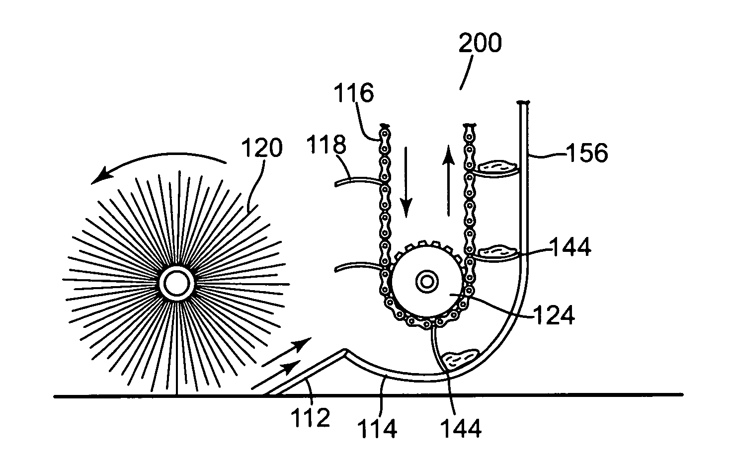
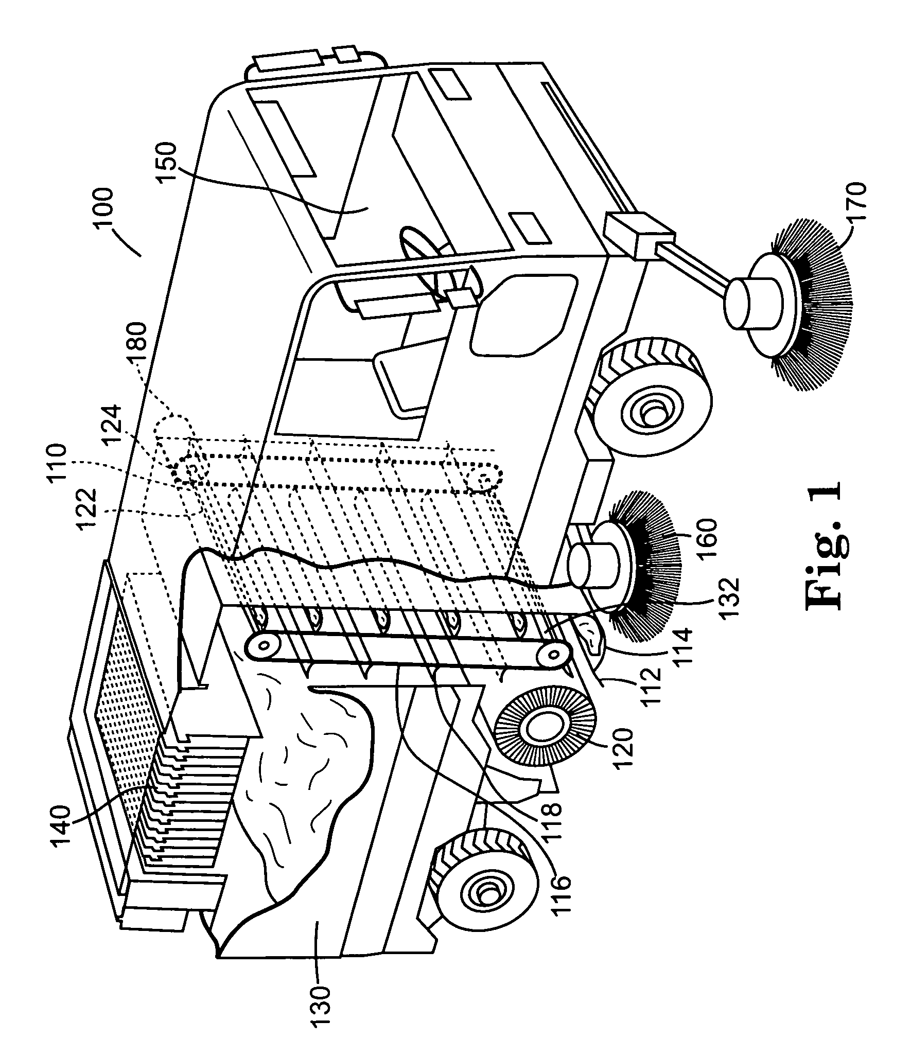
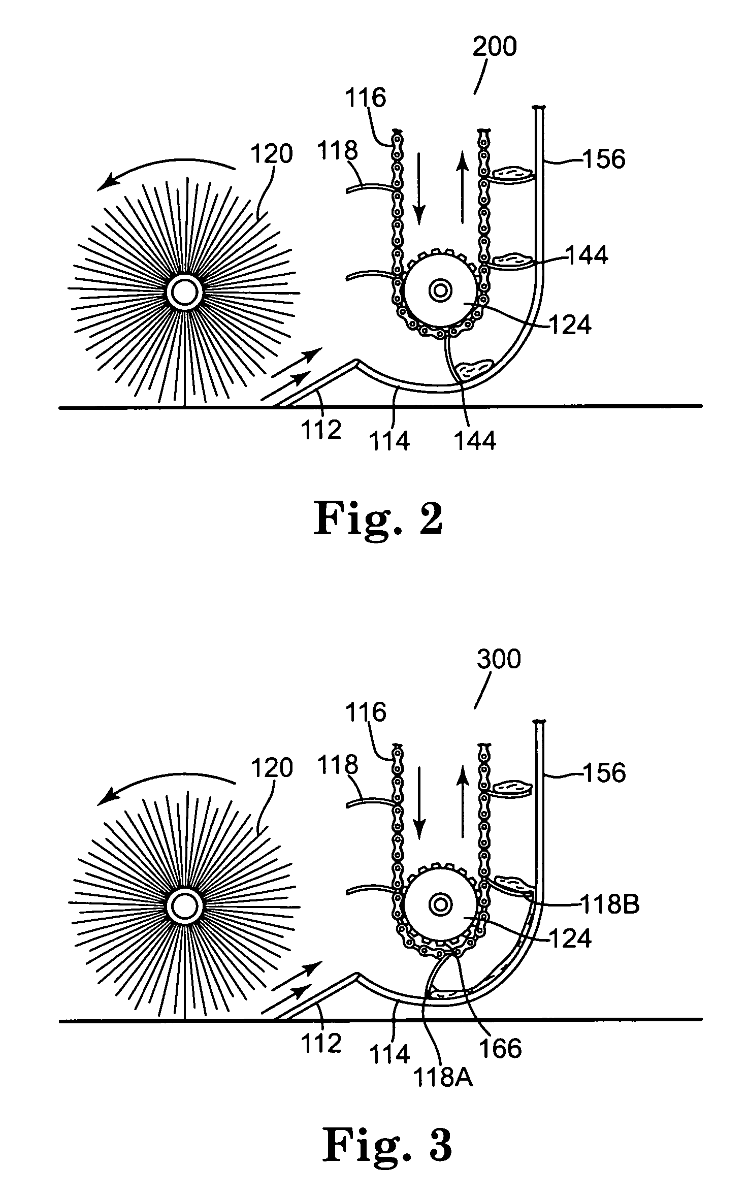
The present invention is a street sweeper with a vertical chain driven conveyor apparatus that can compensate for uneven chain wear and maintain tension in the chains. The sweeper may also have a manual mechanical adjustment mechanism or an automatically adjusting hydraulic or pneumatic adjustment system to ensure the chains remain tensioned. The conveyor apparatus may also include a locking adjustment mechanism to prevent the chains from falling out of tension when the sweeper is turned off. The apparatus may also include a roller brush for directing debris to an intermediate hopper and a plurality of flights associated with each chain to elevate debris from the intermediate hopper to a main hopper. The chain adjusting mechanisms may include a hydraulic cylinder or a pneumatic cylinder with an extendible shaft to provide and maintain tension in the chains. The locking adjustment mechanism may be a tensioned ratchet pawl and pin engagement or an accumulator associated with a fully enclosed pressurized system. The technical effects of the present invention include improved sweeping efficiency, reduced wear and tear on the chains, and improved debris handling.

Problems solved by technology

Vertical chain driven conveyors suffer a drawback that horizontal chain conveyors are not as hampered by.
However, in a vertical chain driven conveyor system, tension must be maintained in the chains at all times, otherwise the chain will fall off the bottom sprocket leading to perhaps catastrophic damage to the conveyor system.
Additionally, if the chains are not held in tension, the operation of the conveyor will be impeded or ultimately fail.
Chain adjustment is laborious, time consuming, and to the unskilled, dangerous.

Method used


Image

  • Chain driven conveyor having automatic tensioning street sweeping method and system
  • Chain driven conveyor having automatic tensioning street sweeping method and system
  • Chain driven conveyor having automatic tensioning street sweeping method and system

Examples


Embodiment Construction

[0058]In the following description of the illustrated embodiments, reference is made to the accompanying drawings which form a part hereof, and in which is shown by way of illustration, various embodiments in which the invention may be practiced. It is to be understood that other embodiments may be utilized, and structural and functional changes may be made without departing from the scope of the present invention.

[0059]The present invention provides a street sweeper having a vertical chain driven conveyor apparatus. The term “chain” needs to be interpreted broadly in this application, since it does not refer only to link chains, but can include belts and any other drive means or drive bands, which is subject to wear and stretching. The vertical chain driven conveyor apparatus may be provided with a multiple jointed shaft to compensate for chain wear over the life of the chains. The street sweeper may also be provided with a manual mechanical adjustment mechanism to ensure that the ...


PUM


Abstract

Disclosed herein is a street sweeper having a vertical chain driven conveyor apparatus. The vertical chain driven conveyor apparatus is provided with a jointed shaft to compensate for chain wear over the life of the chains. The vertical chain driven conveyor apparatus is provided with an automatically adjusting chain tension adjustment system. The vertical chain driven conveyor apparatus is provided with locking adjustment mechanism to prevent the chains from losing tension when the sweeper is turned off. An initialization program is operable to restore chain tension when the street sweeper is started and prevent sweeping operations until a desired chain tension has been indicated.

Description

CROSS-REFERENCE TO RELATED APPLICATIONS[0001]This is a Non-Provisional (Utility) patent application of provisional application Ser. No. 60 / 470586 filed May 15, 2003.BACKGROUND OF THE INVENTION[0002]1. Field of the Invention.[0003]The present invention relates to a street sweeper having a vertical chain driven conveyor apparatus. The vertical chain driven conveyor apparatus may be provided with an automatic chain adjustment system. The vertical chain driven conveyor apparatus also may be provided with a locking adjustment mechanism to prevent the chains losing tension when the sweeper is turned off. The sweeper may also be provided with an initialization program to restore tension in the chains upon startup and prevent sweeping operations until a desired chain tension has been indicated.[0004]2. Description of Related Art.[0005]Street sweepers are a common necessity to maintaining the safety and beauty of streets and highways throughout the world. Street sweepers come in a variety of...

Claims


Application Information

Patent Timeline
Patent Type & Authority Patents(United States)
IPC IPC(8): B65G39/16E01H1/04
CPCE01H1/042
Inventor HANSEN, KARL ROBERTBLOCK, CRAIG DANIEL
Owner TENNANT COMPANY
Learn More