
Threaded fastener assembly and method of locking a threaded fastener

a threaded fastener and threaded technology, which is applied in the direction of threaded fasteners, screwdrivers, manufacturing tools, etc., can solve the problems of insufficient tightening of locking wires, and inability to adjust the tension of locking wires at elevated temperatures. achieve the effect of increasing the tension of locking wires

Inactive Publication Date: 2013-08-01
ROLLS ROYCE PLC
View PDF43 Cites 2 Cited by
  • Summary
  • Abstract
  • Description
  • Claims
  • Application Information

AI Technical Summary

Benefits of technology

The patent is about a new locking wire that can be easily tensioned by heating it. This wire can be adjusted to different levels of tension by heating it at different temperatures. The locking wire can be cooled back down to its original temperature, and the tension will remain. This makes it easier to adjust the tension of the wire than with previous wires, which could only be adjusted by length. Additionally, a two-way shape memory alloy can be used to adjust the tension by altering the temperature, and a one-way shape memory alloy can be used to increase tension by heating the wire and keeping it hot. Overall, this allows for easier and more precise adjustment of the tension of the locking wire.

Problems solved by technology

However, once tightened, threaded fasteners may subsequently rotate about their principal axis due to vibration for example, and thereby loosen over time.
However, it is difficult to tighten the locking wire to a sufficient extent to ensure that the bolt is locked in place, since the wire will be at least slightly elastic, and a small rotation of the bolt may be sufficient for it to become loose to an unacceptable degree.
The wire may also become slack at elevated temperatures (i.e. temperatures above the temperature at which the locking wire is installed), due to thermal expansion of the wire material.
This is particularly problematic where the wire is used to secure a threaded fastener in an article which experiences high temperatures in use, such as a gas turbine engine.

Method used


Image

  • Threaded fastener assembly and method of locking a threaded fastener
  • Threaded fastener assembly and method of locking a threaded fastener

Examples


Embodiment Construction

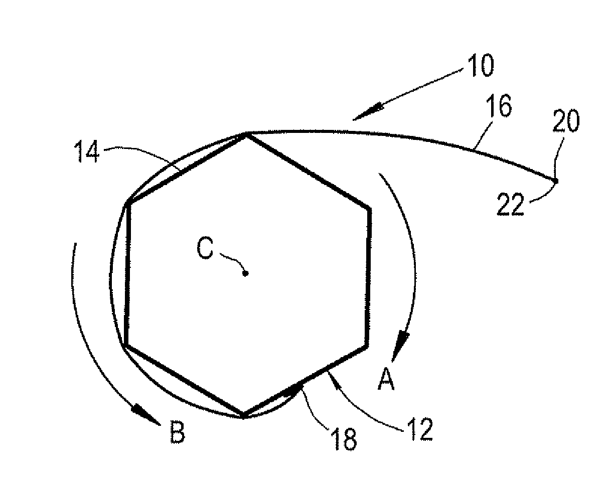
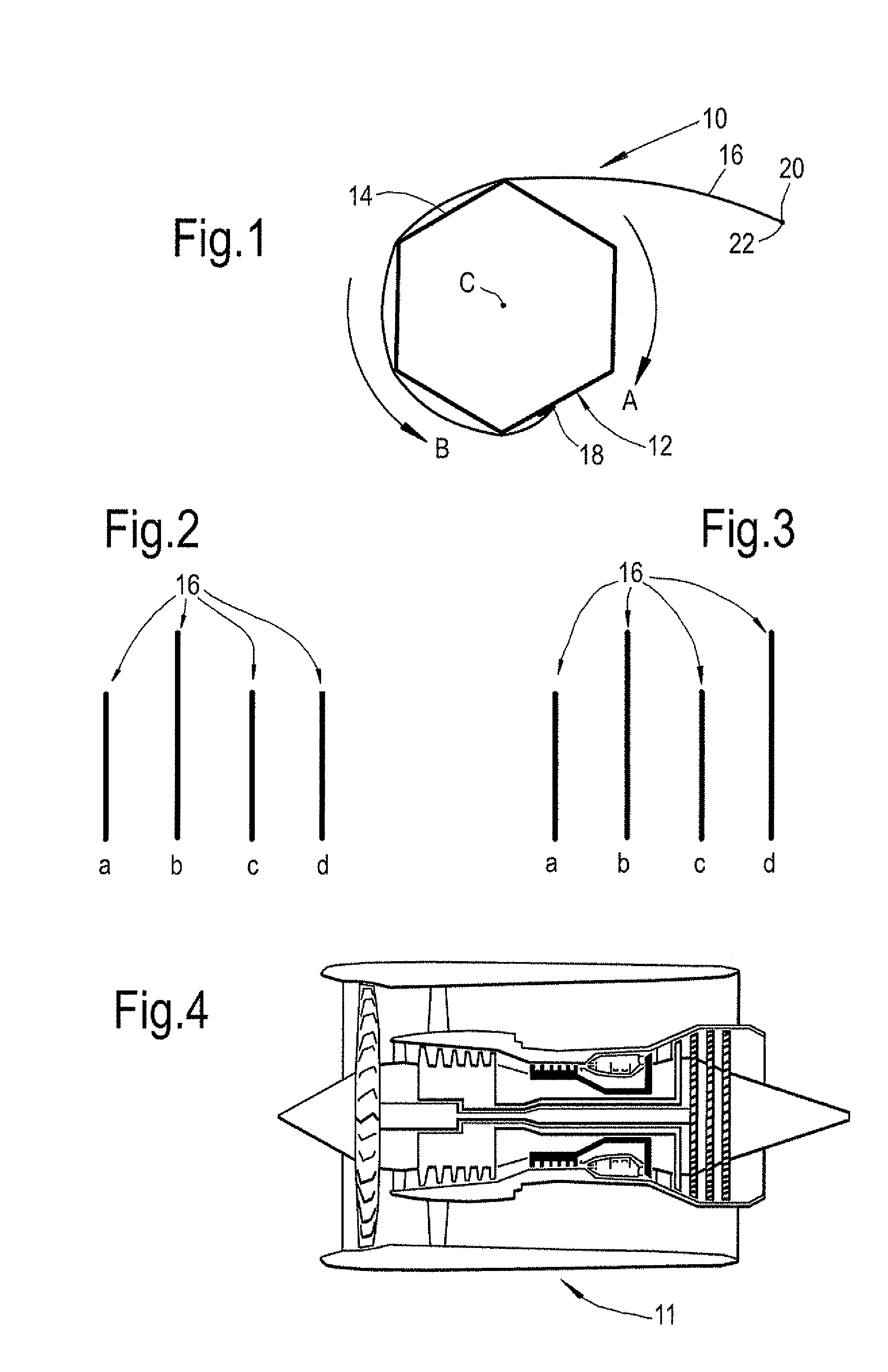
[0033]FIG. 1 shows a fastener assembly 10 in accordance with the present invention in a tightened and locked position on an article 11. The fastener assembly 10 includes a fastener in the form of a bolt 12 having a head 14. The bolt 12 could be formed of any suitable material such as steel or Titanium. The fastener assembly 10 further includes a locking wire 16.

[0034]The locking wire 16 is made of a shape memory alloy (SMA) material. The SMA material could either be a one-way SMA material (such as that shown in FIGS. 2a to 2b), or a two way SMA material (such as that shown in FIGS. 3a to 3b), In either case, the wire 16 may comprise a single strand of SMA material, or may comprise a plurality of strands that have been woven to form a thread.

[0035]SMA materials are characterised by undergoing a transition from a martensite phase to an austenite phase on heating to a transition temperature or range of temperatures. The term “martensite” will be understood to refer to a material having...


PUM

PropertyMeasurementUnit
start temperatureaaaaaaaaaa
finish temperature Afaaaaaaaaaa
Ms temperatureaaaaaaaaaa

Abstract

A threaded fastener assembly comprising a threaded fastener (12) and a length of locking wire (16) comprising a shape memory alloy material. The locking wire (16) is pre-worked such that the wire contracts when the locking wire (16) is heated from a temperature below an austenite start temperature (As) of the locking wire (16) to a temperature above the austenite start (As) temperature of the locking wire (16).

Description

BACKGROUND OF THE INVENTION[0001]The present invention relates to a threaded fastener assembly and a method of locking a threaded fastener in a tightened position.[0002]Threaded fasteners such as bolts and nuts can be used to fasten two or more articles together. However, once tightened, threaded fasteners may subsequently rotate about their principal axis due to vibration for example, and thereby loosen over time.[0003]Threaded fasteners may therefore be locked in the tightened position using a locking wire. In this method, a threaded fastener such as a bolt is located in an aperture of an article to be fastened, and is tightened by rotation about a principal axis until the head of the bolt contacts the surface of the article, and the required torque is then applied. A first end of a locking wire is fixed to the bolt, usually either to a side face of the head or underneath the head. Once the bolt is tightened, the locking wire is wrapped partly round the head, for example in a cloc...

Claims


Application Information

Patent Timeline
Patent Type & Authority Applications(United States)
IPC IPC(8): F16B39/20
CPCF16B39/20Y10T29/49948F16B39/10F16B1/0014F16B2200/77
Inventor MARSHALL, LUKE
Owner ROLLS ROYCE PLC
Learn More