
Heater and motor control

a motor control and heater technology, applied in the direction of electric controllers, controllers with particular characteristics, instruments, etc., can solve the problems of poor temperature regulation, limited control of temperature, and inability to achieve truly versatile systems with fixed pid control

Inactive Publication Date: 2011-05-19
BRUDEVOLD MARK J
View PDF7 Cites 1 Cited by
  • Summary
  • Abstract
  • Description
  • Claims
  • Application Information

AI Technical Summary

Benefits of technology

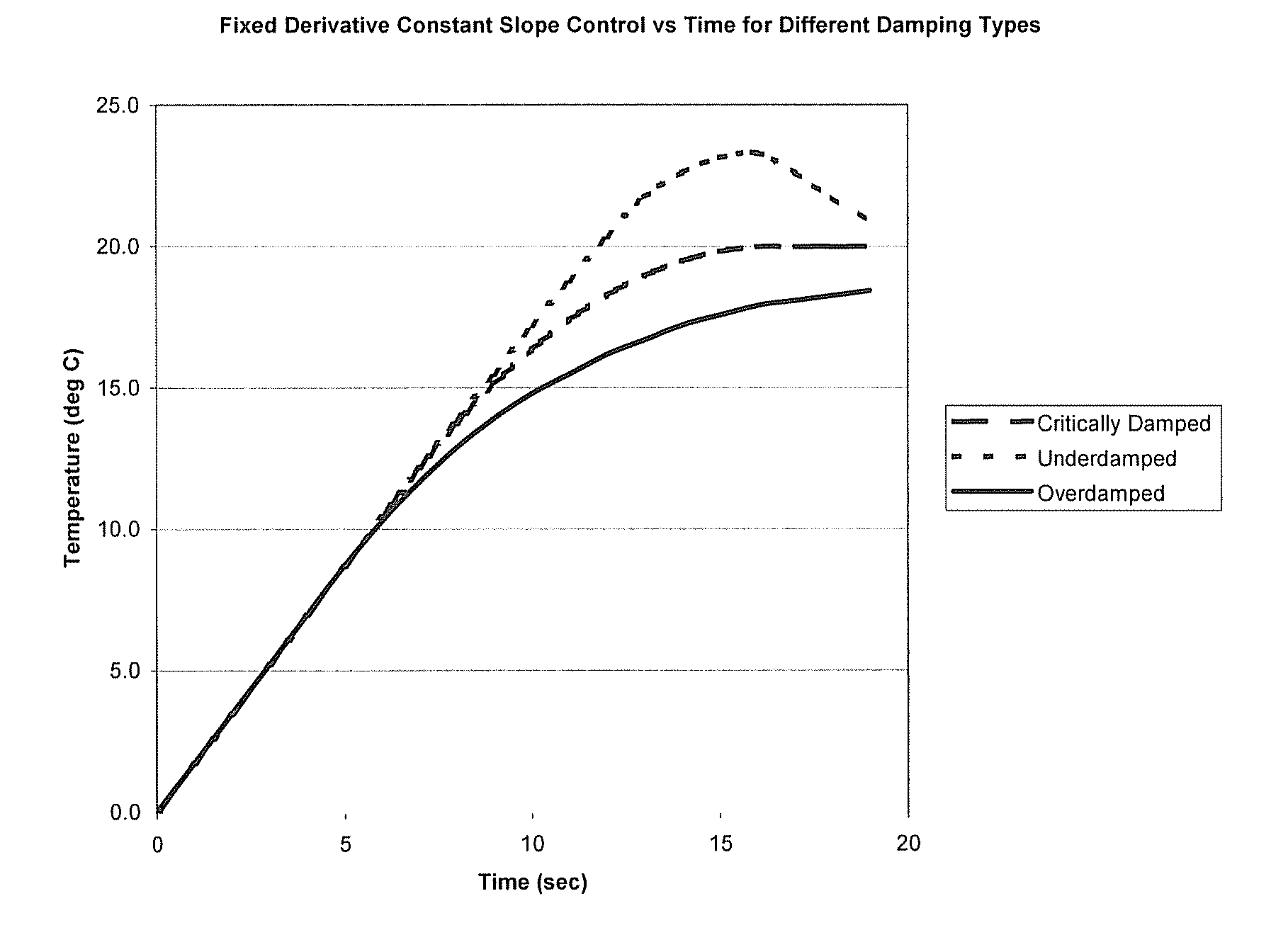
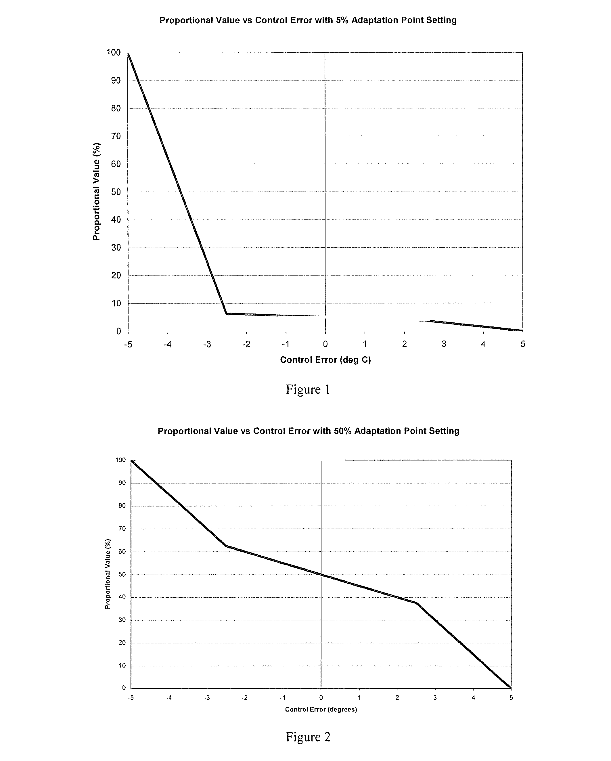
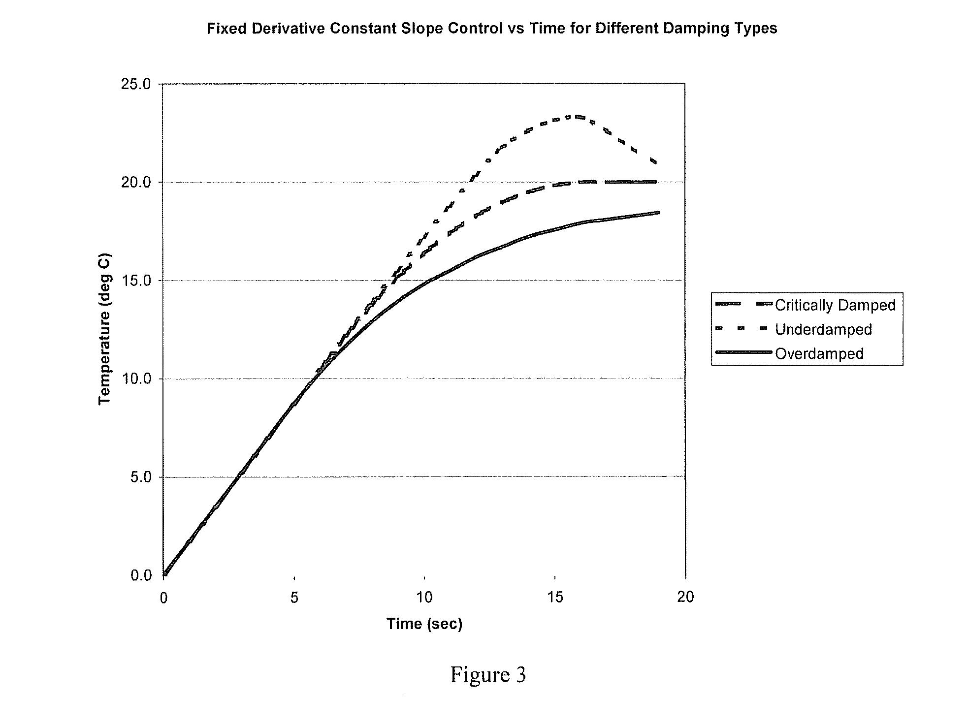
[0011]The control method of the instant invention uses the following scheme:Control Value(CV)=Proportional Value(PV)+Derivative Value(DV)+Derivative Correction(DC)Where PV goes from 0 to MAX and operates over a very narrow band—in a temperature control example plus or minus 1 degree C. from the setpoint and is used to stabilize CV and enforce the setpoint. DV goes from −MAX to MAX and is exponentially decayed over a time constant to weigh the most recent values much heavier than older values. This allows the control to see the real derivative despite a large step size which might otherwise mask it and all within a small time window. DC goes from −MAX to MAX and makes this scheme work for any situation. The desired derivative is defined based on the graph. This then adjusts to compensate when the slope is not following the ideal definition. Averaging for this is different from DV and occupies a broader time range.

Problems solved by technology

While most are generally effective, they all have their own quirks and deficiencies.
This technique is limited in how well it controls temperature, particularly with fast temperature changes, because there is no prevention of overshoots and undershoots due to the momentum of the heater.
Any time a system is operated in a different way, such as heating a different material or dispensing at a different flow rate, the values are no longer optimal and may result in poor regulation of temperature.
The end result is that a truly versatile system is not possible with fixed PID control.

Method used


Image

  • Heater and motor control
  • Heater and motor control
  • Heater and motor control

Examples


Embodiment Construction

[0016]Adaptive control techniques were invented for the Temperature Control Modules to provide a platform that can control any heater in the various setups it may see in the field. The limitations of PID control are overcome by taking a different approach to temperature control.

[0017]In creating the control algorithm, it was noted that temperature control can be broken into two crucial aspects: control of slope to reach the setpoint, and steady state control after the setpoint is reached. These can be treated somewhat independently of each other, particularly for very slow systems such as Graco's THERM-O-FLOW platen. The control algorithm needed to address this fact in order to be successful.

[0018]The integral term is problematic in controls and can really be considered the equivalent of a band-aid because it is a summation of past errors. The problem with the integral term is that it has a tendency to create oscillations in the control by adding up to a value that is too large when...


PUM


Abstract

The control method uses the following scheme: Control Value (CV)=Proportional Value (PV)+Derivative Value (DV)+Derivative Correction (DC), where PV goes from 0 to MAX and operates over a very narrow band—in a temperature control example plus or minus 1 degree C. from the setpoint and is used to stabilize CV and enforce the setpoint. DV goes from −MAX to MAX and is exponentially decayed over a time constant to weigh the most recent values heavier than older values. This allows the control to see the real derivative despite a large step size which might otherwise mask it and within a small time window. DC goes from −MAX to MAX and makes this scheme work for any situation. The desired derivative is defined based on the graph. This then adjusts to compensate when the slope is not following the ideal definition.

Description

TECHNICAL FIELD[0001]This application claims the benefit of U.S. Application Ser. No. 61 / 077,663, filed Jul. 2, 2008, the contents of which are hereby incorporated by reference.BACKGROUND ART[0002]Various methods of control have been used to control motors, heater and the like. While most are generally effective, they all have their own quirks and deficiencies.[0003]The most basic form of control is on / off. Under this control strategy, heat is turned fully on when the temperature is below the setpoint and fully on when the temperature is above the setpoint. This technique is limited in how well it controls temperature, particularly with fast temperature changes, because there is no prevention of overshoots and undershoots due to the momentum of the heater.[0004]On / off control is used in situations where there is no software (i.e. basic thermostats), very limited software, or the hardware is unable pulse a duty cycle over a short period of time. Older microwaves, for example, use an ...

Claims


Application Information

Patent Timeline
Patent Type & Authority Applications(United States)
IPC IPC(8): G05B13/02
CPCG05B11/36G05B11/42
Inventor BRUDEVOLD, MARK J.
Owner BRUDEVOLD MARK J
Learn More