Methods systems and apparatus for analyzing complex systems via prognostic reasoning

Active Publication Date: 2011-05-19
HONEYWELL INT INC
View PDF16 Cites 96 Cited by
  • Summary
  • Abstract
  • Description
  • Claims
  • Application Information

AI Technical Summary

Benefits of technology

[0012]The analysis system can include one or more simple diagnostic and prognostic monitors (SDPMs), one or more advanced diagnostic and prognostic monitors (ADPMs) and a maintenance computer (MC). The SDPM (s) are each designed to process sensor data from at least one of the sensors and generate binary evidence of a sensed event. The ADPM(s) are each designed to process sensor data from at least one of the sensors and generate at least one form of complex evidence of a sensed event. The complex evidence can include one or more of: a condition indicator (CI), a health indicator (HI), and a prognostic indicator (PI).
[0013]The maintenance computer (MC) is communicatively coupled to the SDPM(s) and the ADPM(s). The MC includes an advanced diagnostics and prognostics reasoner (ADPR) module. The ADPR module is designed to process the binary evidence

Problems solved by technology

However, the PR module 35 does not normally provide optimal support for dia

Method used


Image

  • Methods systems and apparatus for analyzing complex systems via prognostic reasoning
  • Methods systems and apparatus for analyzing complex systems via prognostic reasoning
  • Methods systems and apparatus for analyzing complex systems via prognostic reasoning

Examples


Embodiment Construction

[0023]The following detailed description is merely exemplary in nature and is not intended to limit the invention or the application and uses of the invention. As used herein, the word “exemplary” means “serving as an example, instance, or illustration.” Any embodiment described herein as “exemplary” is not necessarily to be construed as preferred or advantageous over other embodiments. Furthermore, there is no intention to be bound by any theory presented in the preceding background or the following detailed description.

[0024]Overview

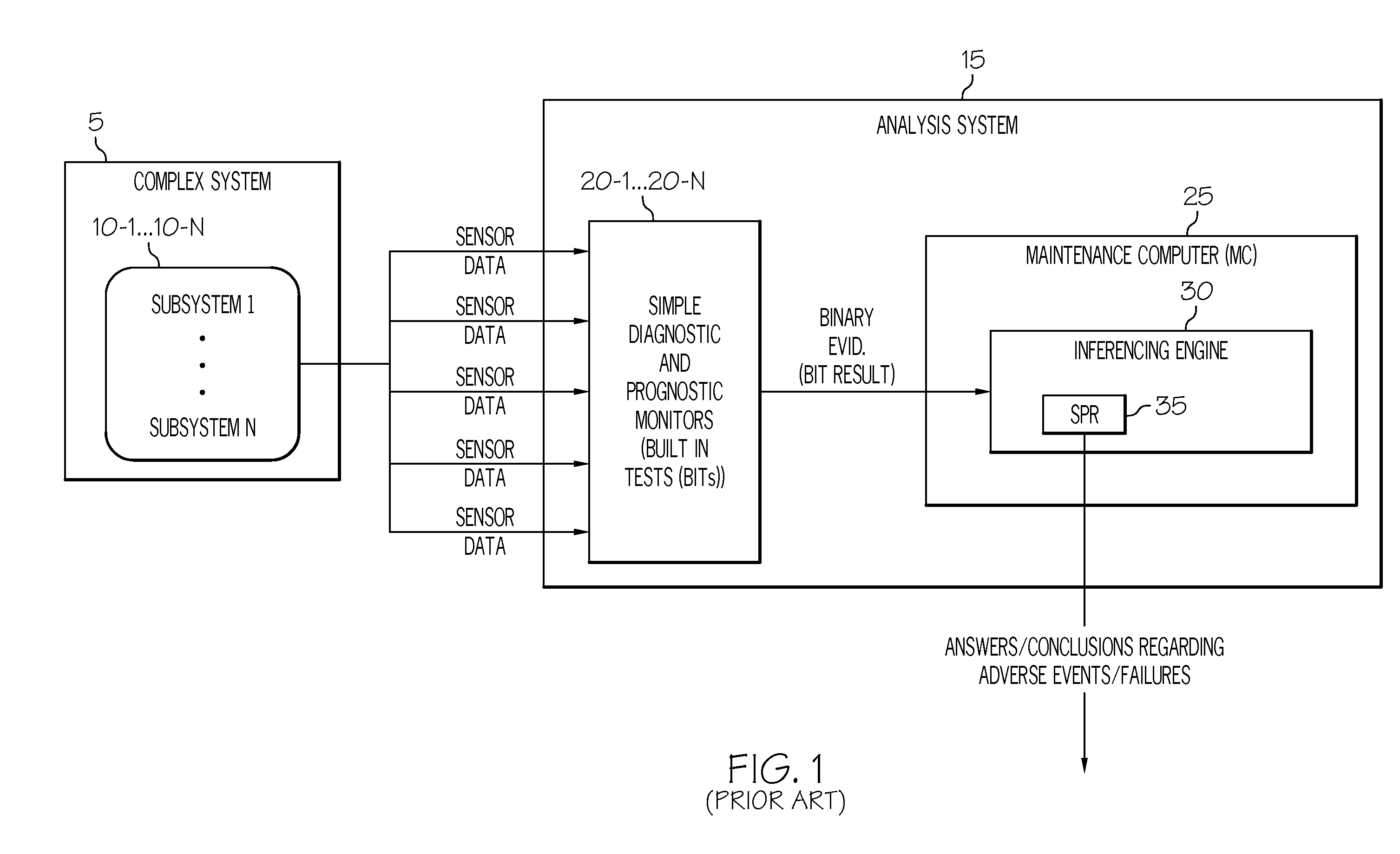
[0025]One drawback of the analysis system 15 described above with reference to FIG. 1 is that the SDPMs 20 used to interpret sensor data each generate simple binary evidence (i.e., BIT results) only. However, in many cases, simple binary evidence is not good enough to identify certain adverse events or failures in the complex system 5 or one of its sub-systems 10. For example, simple binary evidence is insufficient to identify “complex adverse events” ...


PUM


Abstract

Methods and apparatus are provided for analyzing a complex system that includes a number of subsystems. Each subsystem comprises at least one sensor designed to generate sensor data. Sensor data from at least one of the sensors is processed to generate binary evidence of a sensed event, and complex evidence of a sensed event. The complex evidence has more sophisticated mathematical properties than the binary evidence. The complex evidence comprises one or more of: a condition indicator (CI), a health indicator (HI), and a prognostic indicator (PI). A system fault model (SFM) is provided that defines statistical relationships between binary evidence, complex evidence, and an underlying failure mode (FM) that is occurring in the complex system. The binary evidence and the complex evidence are processed to identify failure modes taking place within one or more of the subsystems. Based on the binary evidence and the complex evidence and the SFM, diagnostic conclusions can be generated regarding adverse events that are taking place within the complex system, and prognostic conclusions can be generated regarding adverse events that are predicted to take place within the complex system.

Description

TECHNICAL FIELD[0001]The present invention generally relates to diagnosis and prognosis of complex systems, and more particularly relates to a monitoring system and reasoning architecture for identifying, diagnosing and prognosing adverse events or failures that might be occurring in a complex system and / or in one or more of its subsystems.BACKGROUND[0002]In complex systems that include multiple subsystems, such as an electrical plant or a vehicle such as a ship, aircraft or spacecraft, it is desirable to identify adverse events or failures that might be occurring in one or more of its subsystems. For instance, vehicle health monitoring systems are often used to monitor various health characteristics of vehicle systems.[0003]FIG. 1 is a block diagram that illustrates a conventional complex system 5 and analysis system 15. The complex system 5 includes a number (1 . . . N) of subsystems 10, and each subsystem 10 includes one or more sensors or other monitors (not shown). Each sensor / ...

Claims


Application Information

Patent Timeline
IPC IPC(8): G06F7/00G06F15/00G06F17/18
CPCG05B23/0251G07C5/085G06N5/04
Inventor MYLARASWAMY, DINKARHADDEN, GEORGE DANIEL
Owner HONEYWELL INT INC
Why Eureka
Try Eureka