Method of detecting a fault attack

Active Publication Date: 2011-05-19
STMICROELECTRONICS SRL
View PDF8 Cites 7 Cited by
  • Summary
  • Abstract
  • Description
  • Claims
  • Application Information

AI Technical Summary

Benefits of technology

[0010]It is an aim of embodiments of the present invention to a

Problems solved by technology

However, there are difficulties in implementing

Method used


Image

  • Method of detecting a fault attack
  • Method of detecting a fault attack
  • Method of detecting a fault attack

Examples


Embodiment Construction

[0026]For clarity, only those steps and elements useful in an understanding of the invention have been represented in the figures and will be described in detail. In particular, the circuitry for resetting an integrated circuit or rendering it inactive upon detection of one or more fault injections has not been detailed, the invention being applicable to any such circuits. Furthermore, the primary functions of the integrated circuit being protected have not been described in detail, the invention being compatible with integrated circuits implementing any sensitive functions, such as encryption or decryption, or other functions involving sensitive data.

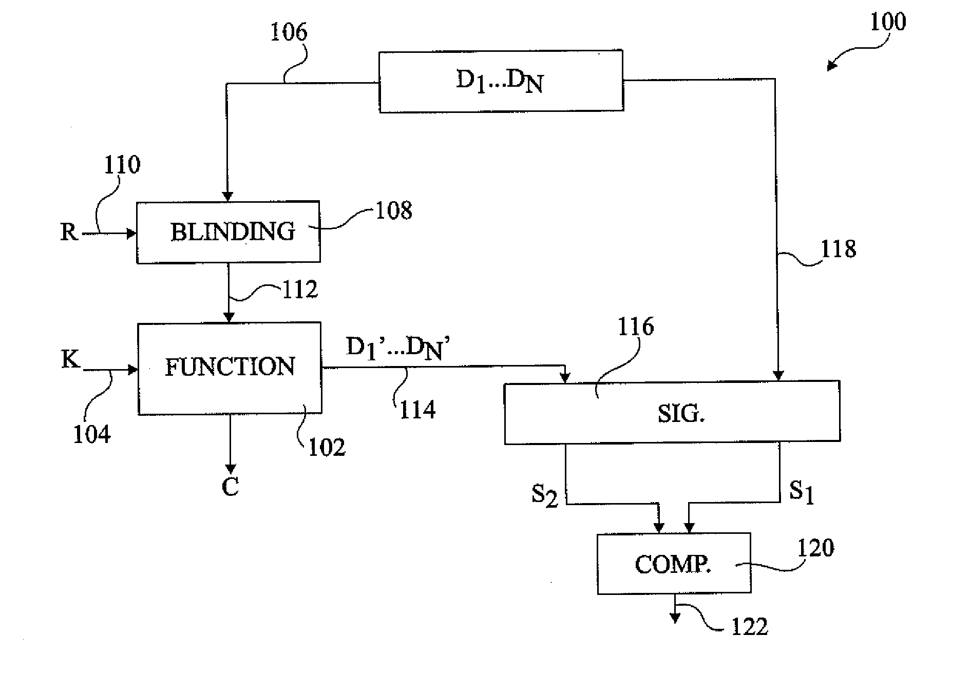
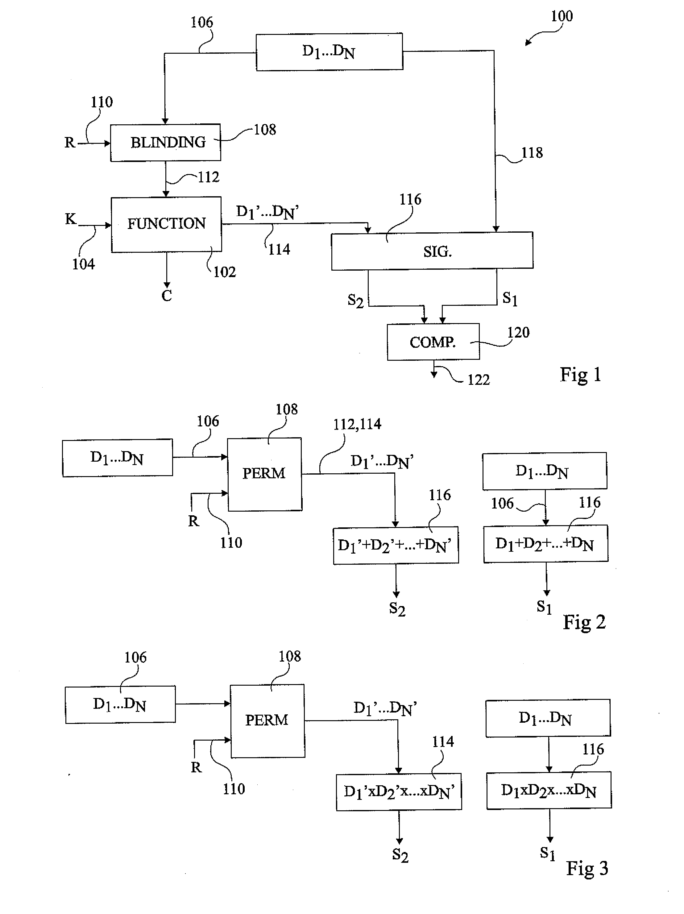
[0027]FIG. 1 illustrates a circuit 100 comprising a function unit 102, which, for example, implements an algorithm involving sensitive data, such as an encryption key or the like. In the present example, unit 102 receives a key K on an input line 104.

[0028]A group of data values D1 to DN are provided on a line 106 to a blinding block 1...


PUM


Abstract

A method of detecting a fault attack including generating a first signature of a first group of data values by performing a single commutative non-Boolean arithmetic operation between all the data values of the first group; generating a second set of data values by performing a permutation of the first set of data values; generating a second signature of the second group of data values by performing said single commutative non-Boolean arithmetic operation between all the data values of the second group; and comparing the first and second signatures to detect a fault attack.

Description

CROSS REFERENCE TO RELATED APPLICATIONS[0001]This application claims the priority benefit of French patent application Ser. No. 09 / 58140, filed on Nov. 18, 2009, entitled “Method of Detecting a Fault Attack,” which is hereby incorporated by reference to the maximum extent allowable by law.BACKGROUND OF THE INVENTION[0002]1. Field of the Invention[0003]The present invention relates to a method and circuitry for detecting fault attacks, and in particular to method and circuitry providing detection based on signatures.[0004]2. Discussion of the Related Art[0005]Integrated circuits may comprise circuitry that is considered sensitive in view of the security of the data it manipulates, such as authentication keys, signatures, etc., or in view of the algorithms it uses, such as encryption or decryption algorithms. Such information is desired to be kept secret, meaning that it should not be communicated to or otherwise be detectable by third parties or unauthorized circuits.[0006]A common p...

Claims


Application Information

Patent Timeline
IPC IPC(8): G06F11/34
CPCH04L9/004H04L2209/04H04L9/06
Inventor TEGLIA, YANNICK
Owner STMICROELECTRONICS SRL
Why Eureka
Try Eureka