
Cryopreservation device

a cryopreservation and device technology, applied in the field of cryopreservation devices, can solve the problems of increasing the number of times the ampoule or straw tube suffers damage, affecting the work efficiency of operators, so as to reduce the burden of operators and prevent confusion. , the effect of improving workability

Active Publication Date: 2011-05-26
NIPPON SANSO CORP
View PDF12 Cites 23 Cited by
  • Summary
  • Abstract
  • Description
  • Claims
  • Application Information

AI Technical Summary

Benefits of technology

[0036]According to the present invention, when an identification management number of the target ampoule is input to the input apparatus, the gripper head of the handling robot operates and pulls out the ampoule storing tool that stores the target ampoule, inserts it into the ampoule-putting-in / out work hole, and shove it until the target ampoule is exposed from the opening edge of the ampoule-putting-in / out work hole, and then stops. At this time, the bar-code readers mounted to the work table read the bar-code of the ampoule. Meanwhile, the control apparatus compares the identification management number from the bar-code readers with the identification management number from the input apparatus, and output the indication in the case where the both are matched to one another. After the confirmation of this indication, an operator takes the target ampoule out from the ampoule storing tool.
[0037]Therefore, it is possible to automatically and promptly carry out the identification of the ampoule storing tools and ampoules, and to prevent the confusion of the ampoule storing tools and ampoules.
[0038]In addition, a series of the operations such as pulling out and the insertion of the ampoule storing tool are carried out by the gripper head of the handling robot. Thus, the burden of an operator is reduced, and workability is improved.

Problems solved by technology

Therefore, a lot of samples other than the target cryopreserved sample are exposed to an ambient temperature, and the samples suffer damage due to increase in temperature.
In addition, the number of times the ampoule or straw tube suffers damage increases.
2) The weight of the one storing rack is several kilograms, and therefore, it becomes difficult to take it into or out of the cryopreservation vessel.
Moreover, the housing rack or canister may fall down within the cryopreservation vessel, and the storing box may drop from the housing rack.
3) It is impossible to detect the preservation position of the housing rack or canister inside from the outside of the cryopreservation vessel.
In addition, the sample management is very complicated because a lot of ampoules are stored in the one housing rack or canister.
For this reason, the identification of the ampoule storing tool and ampoule takes long time, and there is a possibility to confuse the ampoule storing tools and ampoules because of human work.

Method used


Image

  • Cryopreservation device
  • Cryopreservation device
  • Cryopreservation device

Examples


Embodiment Construction

Cryopreservation Device

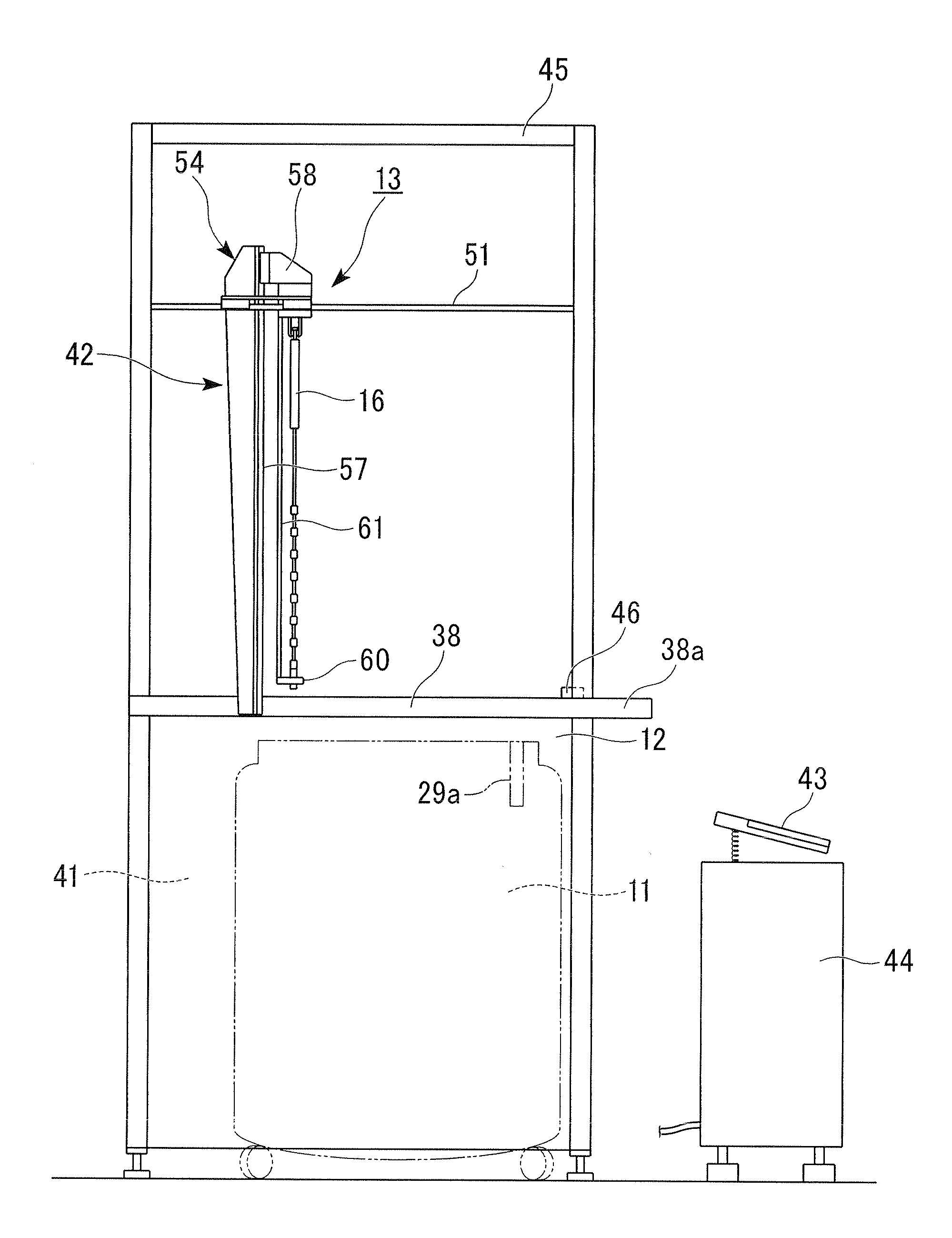
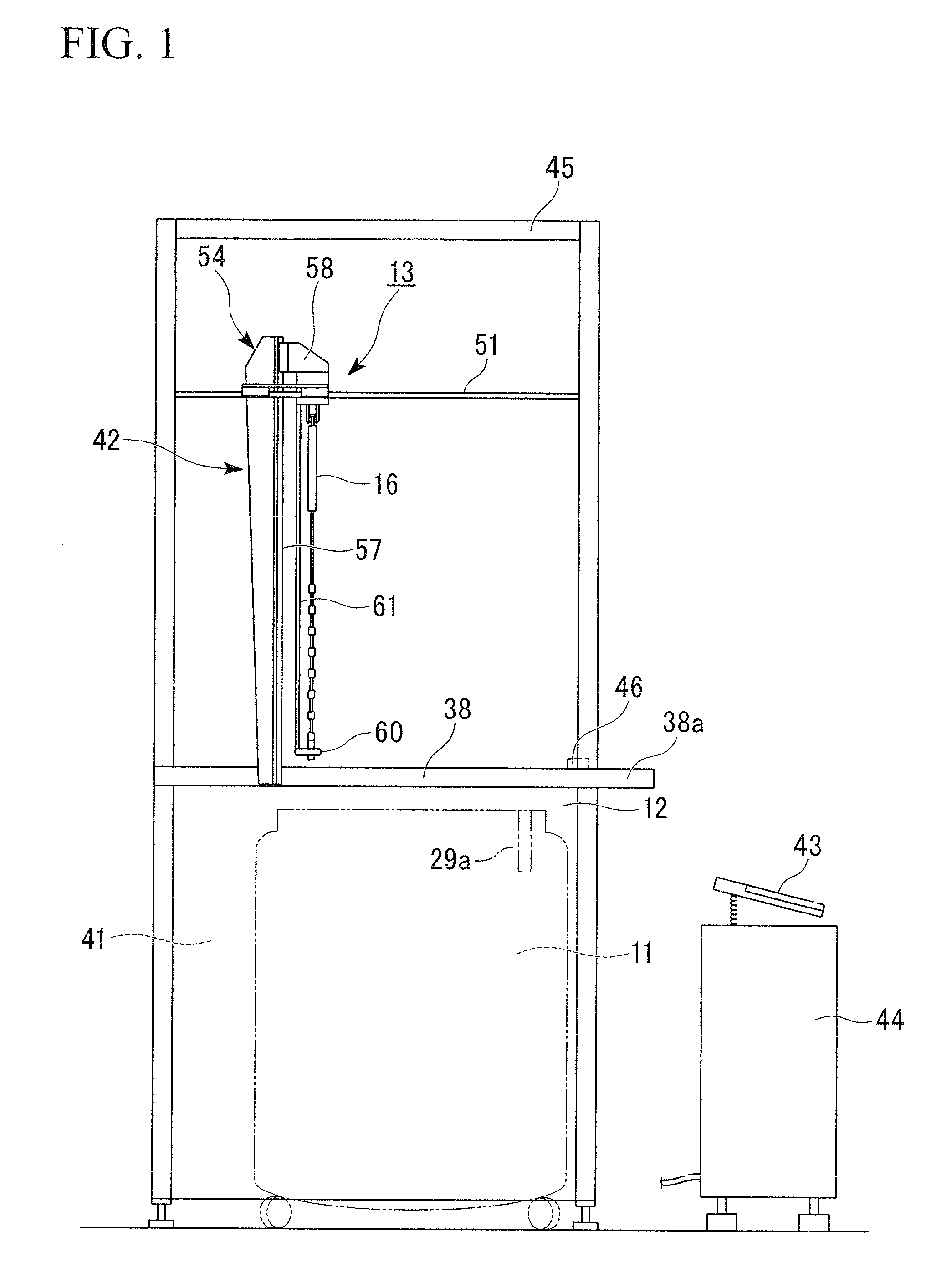
[0066]FIG. 1 to FIG. 8 shows one example of the cryopreservation device of the present invention.

[0067]As shown in FIG. 1, this cryopreservation device is schematically comprised of a cryopreservation vessel 11, a house 12 which houses the cryopreservation vessel 11 and a handling robot 13 provided on the house 12.

(Cryopreservation Vessel)

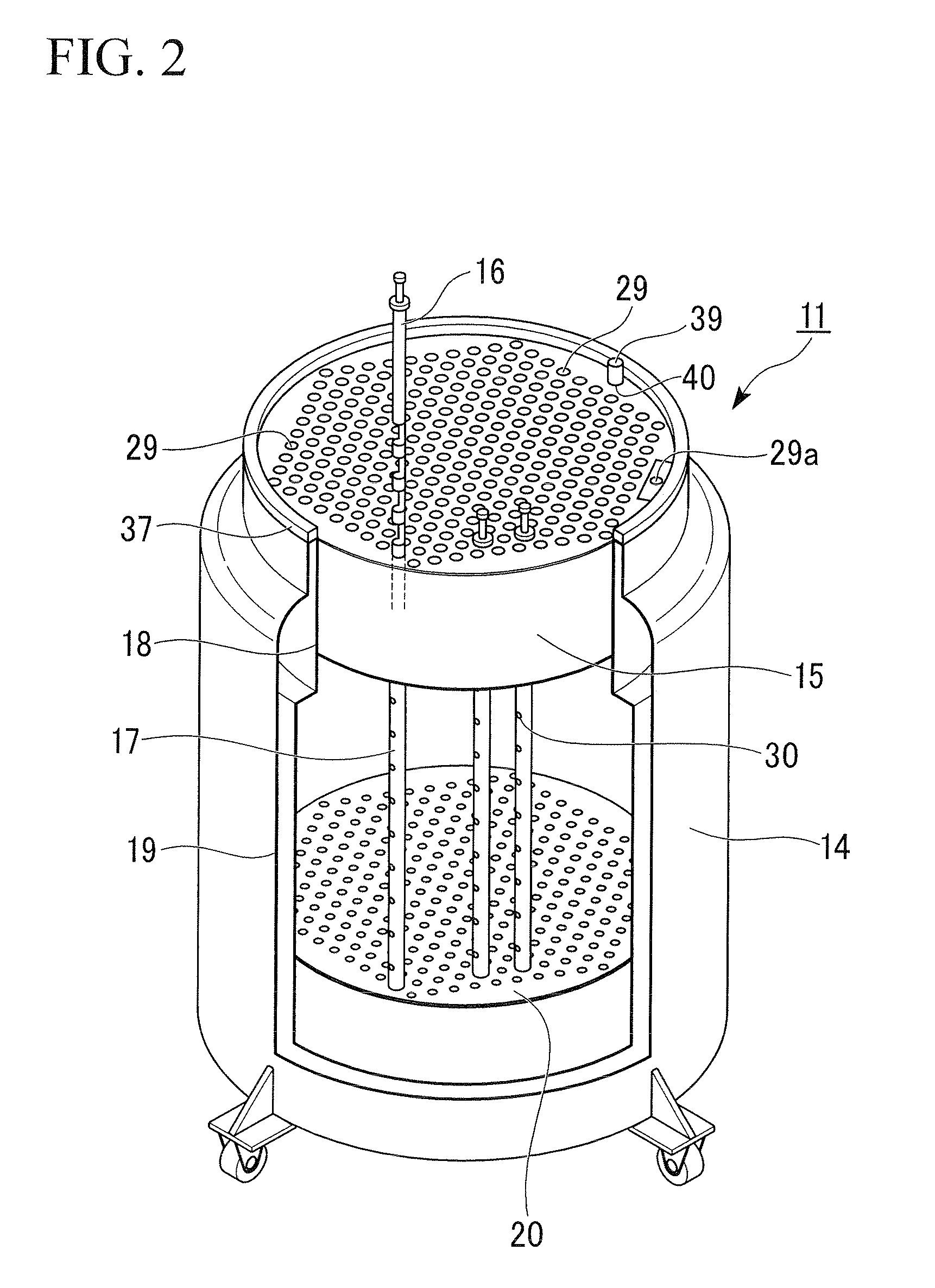
[0068]As shown in FIG. 2, the cryopreservation vessel 11 is comprised of a vessel body 14, a cap 15, ampoule storing tools 16, and sheath tubes 17.

[0069]The vessel body 14 has a double structure formed of an inner vessel 18 and an outer vessel 19 made of stainless steel or the like, and is a vacuum thermal insulating vessel in which a space between the inner vessel 18 and the outer vessel 19 is vacuum.

[0070]A perforated plate 20 is mounted in the vicinity of the bottom portion of the inner vessel 18 of the vessel body 14, and the inner vessel 18 is to be filled close to the perforated plate 20 with the low-temperature liquefi...


PUM


Abstract

A cryopreservation device of the present invention includes: a cryopreservation vessel; a house which houses the cryopreservation vessel; and a handling robot provided on the house, wherein the cryopreservation vessel comprises a vessel body which holds a low-temperature liquefied gas, a cap which closes an opening section of the vessel body and has a plurality of insertion holes formed to pass through in a vertical direction, and ampoule storing tools which are housed so as to be able to pass through the insertion holes of the cap, in which the ampoule storing tools are each comprised of a support pillar and a plurality of ampoule storing sections which are attached to the support pillar so as to be arrayed in a vertical direction of the support pillar, and an ampoule-putting-in / out work hole is formed in the cap so as to pass through in a vertical direction.

Description

TECHNICAL FIELD[0001]The present invention relates to a cryopreservation device used to cryopreserve biological samples such as spermatozoa, embryo, and cells of animals.[0002]Priority is claimed on Japanese Patent Application No. 2008-268770, filed Oct. 17, 2008, the content of which is incorporated herein by reference.BACKGROUND ART[0003]Examples of the prior arts regarding the cryopreservation device include Japanese Unexamined Patent Application, First Publication No. 2005-143873, Japanese Unexamined Patent Application, First Publication No. 2005-156136, and Japanese Unexamined Utility Model Application, First Publication No. Hei 4-15911.[0004]In one of these prior arts, (1) the conformation is adapted, in which a lot of ampoules that include biological samples are stored in a plurality of storing sections of a storing box wherein the storing sections are partitioned, a plurality of these storing boxes are housed in a housing rack, and a plurality of these housing racks that eac...

Claims


Application Information

Patent Timeline
IPC IPC(8): F25B19/00
CPCA01N1/0257F25D25/00F25D3/10
Inventor YOSHIMURA, SHIGEHIROOHTA, HIDETOSHIFUJITA, MAMORU
Owner NIPPON SANSO CORP
Features
  • Generate Ideas
  • Intellectual Property
  • Life Sciences
  • Materials
  • Tech Scout
  • Unparalleled Data Quality
  • Higher Quality Content
  • 60% Fewer Hallucinations
Learn More