Printing apparatus and method for controlling printing apparatus

Inactive Publication Date: 2011-05-26
CANON KK
View PDF8 Cites 0 Cited by
  • Summary
  • Abstract
  • Description
  • Claims
  • Application Information

AI Technical Summary

Benefits of technology

[0027]The present invention is directed to a printing apparatus which can s

Problems solved by technology

Thus, head-finding of the ink for the next color cannot be performed.
Therefore, for conventional head-finding conveyance of an ink ribbon, it is necessary to form wasteful margins B and C, which cannot be used as the transfer region R. Such margins B and C increase the total length of the ink ribbon 105, leading to a

Method used


Image

  • Printing apparatus and method for controlling printing apparatus
  • Printing apparatus and method for controlling printing apparatus
  • Printing apparatus and method for controlling printing apparatus

Examples


Embodiment Construction

[0042]Various exemplary embodiments, features, and aspects of the invention will be described in detail below with reference to the drawings.

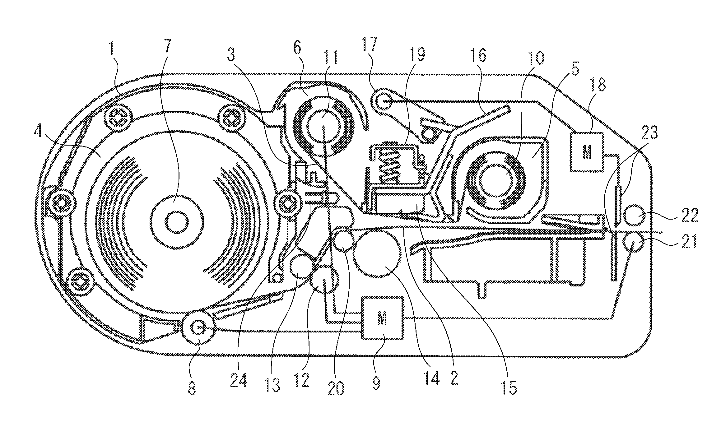
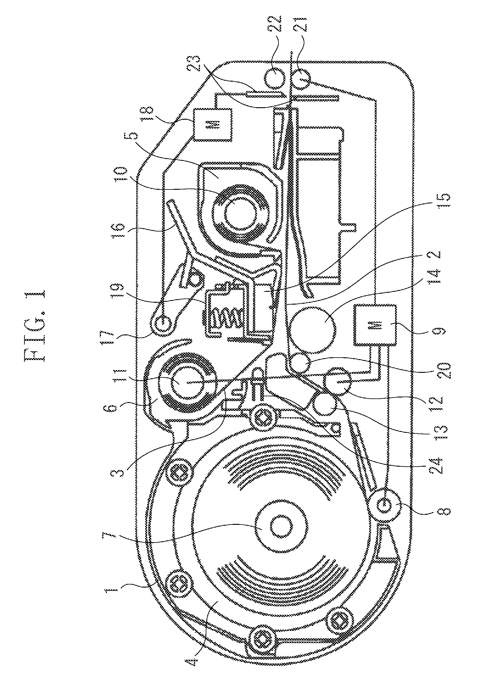
[0043]FIG. 1 is a cross-sectional schematic view of a printing apparatus according to an exemplary embodiment of the present invention. A cassette 1 storing a recording sheet 2 and an ink ribbon 3 includes a roll sheet storage unit 4, a supply ribbon storage unit 5, and a take-up ribbon storage unit 6.

[0044]The roll sheet storage unit 4 stores a roll sheet around which the recording sheet 2 is wound. The supply ribbon storage unit 5 stores a pre-use ink ribbon 3, which is wound around a supply ribbon core 10. The take-up ribbon storage unit 6 stores a used ink ribbon 3, which is wound around a take-up ribbon core 11. The recording sheet 2 may be a paper sheet like printing paper, or may be a plastic sheet like an overhead projector (OHP) sheet, for example.

[0045]A roll sheet core 7 is inserted in a hole section in the middle of the roll sheet. ...


PUM


Abstract

A printing apparatus including a head holding unit movably configured to hold a thermal head so that the thermal head can be in a pressing state pressing against a platen and in a separated state separated from the platen, a conveyance mechanism configured to convey an ink ribbon and a recording sheet which are put on each other to a recording region between the thermal head and the platen, a reflection surface provided on the head holding unit, and a ribbon sensor configured to detect a marker applied on the ink ribbon, the ribbon sensor being provided on an opposite side to the reflection surface across a path of the ink ribbon which has passed through the recording region and been peeled from the recording sheet. The ribbon sensor includes a light emitting element and a light receiving element. The reflection surface is configured so that light incident from the light emitting element reaches the light receiving element in both the separated state and the pressing state.

Description

BACKGROUND OF THE INVENTION[0001]1. Field of the Invention[0002]The present invention relates to a printing apparatus, and more specifically, to a thermal transfer type printing apparatus which includes a unit for detecting a marker on an ink ribbon.[0003]2. Description of the Related Art[0004]Examples of printer printing methods include thermal transfer, in which ink coated on an ink ribbon is thermally transferred onto printing paper using a thermal head. Examples of a thermal printer, which is a printing apparatus that employs a thermal transfer technique, include printers having a unit for detecting a conveyance position on the ink ribbon.[0005]A method in which a thermal printer detects the conveyance position of an ink ribbon will be described using FIGS. 7 to 11. FIG. 7 is a cross-sectional view of a printing mechanism vicinity in a conventional thermal printer.[0006]A thermal head 101 is fixedly supported on a thermal head unit 150. The thermal head unit 150 is rotatable aro...

Claims


Application Information

Patent Timeline
IPC IPC(8): B41J2/325
CPCB41J2/325B41J35/18B41J17/02
Inventor KITAMURA, GEN
Owner CANON KK
Why Eureka
Try Eureka