Stereoscopic image display apparatus and cursor display method

a display apparatus and cursor technology, applied in image analysis, image enhancement, instruments, etc., can solve the problems of user losing the sight of the cursor, unable to recognize which object the cursor is pointing at, and unable to meet the intended operation of the user

Inactive Publication Date: 2011-05-26
CANON KK
View PDF6 Cites 26 Cited by
  • Summary
  • Abstract
  • Description
  • Claims
  • Application Information

AI Technical Summary

Benefits of technology

[0008]The present invention has been made in view of the foregoing problem, and an embodiment of the present invention provides a stereoscopic image display apparatus a

Problems solved by technology

However, there is a problem that it is difficult to recognize which object the cursor is pointing at if a cursor of a two-dimensional plane is simply superimposed and displayed f

Method used


Image

  • Stereoscopic image display apparatus and cursor display method
  • Stereoscopic image display apparatus and cursor display method
  • Stereoscopic image display apparatus and cursor display method

Examples


first embodiment

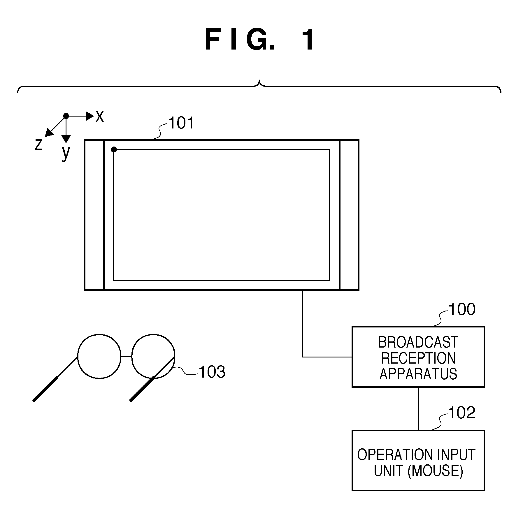
[0024]FIG. 1 is a schematic diagram showing a configuration of a stereoscopic image observation system to which the present invention can be applied. The stereoscopic image observation system of the present embodiment comprises: a stereoscopic image display apparatus including a broadcast reception apparatus 100, a display panel 101, and a mouse 102; and dedicated glasses 103 for stereoscopic observation. The mouse 102 is an example in which a pointing device is applied as an operation input unit. The operation input unit capable of operating the cursor in the stereoscopic image display is not limited to such an illustration, and various configurations, such as a trackball, a coordinate input apparatus, and an arrow key, can be adopted.

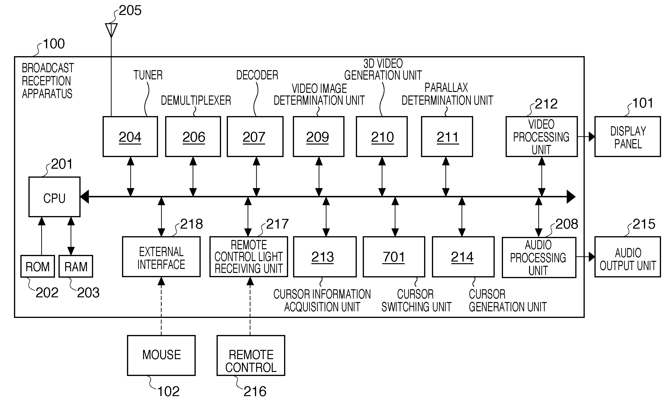
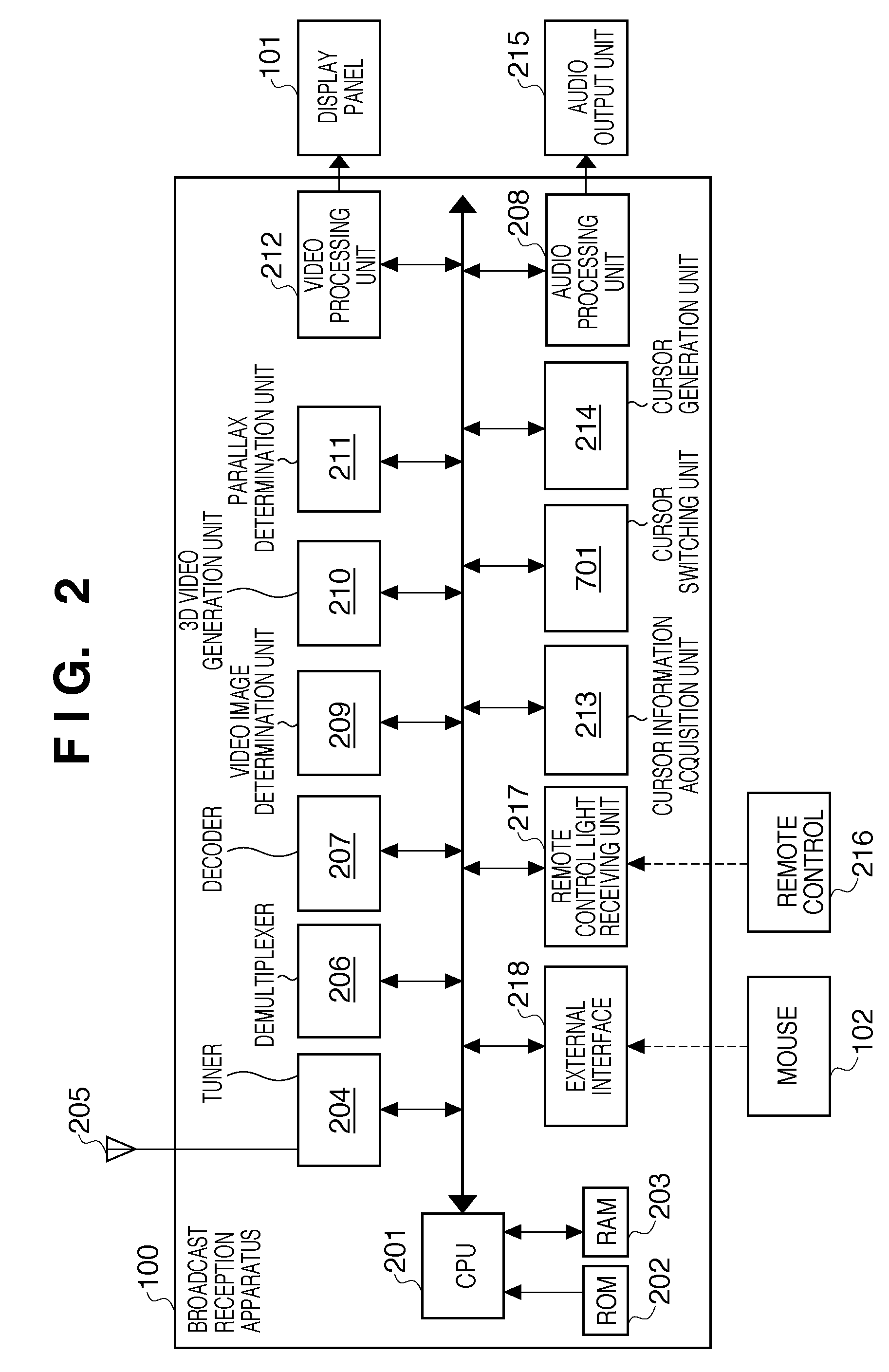
[0025]The broadcast reception apparatus 100 is an apparatus that controls a broadcast reception function in the stereoscopic image observation system according to the present embodiment. For example, a mouse 102 is connected to the broadcast reception...

second embodiment

[0049]A process according to a second embodiment of the present invention will be described. The entire configuration of the stereoscopic image observation system in the second embodiment is the same as in the first embodiment (FIGS. 1 and 2). The description of the common parts as in the first embodiment will be omitted as necessary in the description of the second embodiment.

[0050]In the second embodiment, the cursor switching unit 701 is added (FIG. 7) to the configuration of the first embodiment (FIGS. 3A and 3B). In addition to the process of acquiring the current cursor location, the cursor information acquisition unit 213 of the second embodiment has a function of predicting a location after movement of the cursor (hereinafter, “next cursor location”) at next interrupt timing based on the moving direction and the moving speed of the cursor. Furthermore, the parallax determination unit 211 of the second embodiment determines, for each of the current cursor location and the nex...


PUM


Abstract

A stereoscopic image display apparatus capable of generating a cursor that moves according to user operation to allow stereoscopic view with a stereoscopic image including a set of images with parallax and capable of combining and displaying the cursor on the stereoscopic image acquires a parallax amount of the stereoscopic image at a location where the cursor is combined and displayed on the stereoscopic image and calculates a moving speed of the cursor. The stereoscopic image display apparatus determines whether the cursor is moving based on the calculated moving speed and generates the cursor including a certain predetermined value as the parallax amount of the cursor if it is determined that the cursor is moving. The stereoscopic image display apparatus generates the cursor by setting the parallax amount of the cursor to the parallax amount of the acquired stereoscopic image if it is determined that the cursor is not moving.

Description

BACKGROUND OF THE INVENTION[0001]1. Field of the Invention[0002]The present invention relates to a stereoscopic image display apparatus and a cursor display method.[0003]2. Description of the Related Art[0004]In recent years, a three-dimensional video production environment is organized along with the progress in digital technologies, and three-dimensional (hereinafter “3D”) broadcast has become a reality. In a stereoscopic image display apparatus that receives and displays 3D broadcasts, a film including deflection characteristics is attached to a display panel, and video images for left eye and right eye are displayed in an interlaced format. The observer can observe a display line for left line by the left eye and a display line for right eye by the right eye through deflection glasses to stereoscopically observe the video images. There is also a stereoscopic display apparatus configured to allow the observer to stereoscopically watch the video images by alternately displaying th...

Claims


Application Information

Patent Timeline
IPC IPC(8): H04N13/04G06F3/048G06F3/0481G06F3/0487G06F3/0489
CPCG06T7/0022H04N13/004H04N13/0497G06T2207/10021H04N13/0409H04N13/007G06T7/97H04N13/156H04N13/183H04N13/31H04N13/398
Inventor KIKKAWA, TERUKI
Owner CANON KK
Why Eureka
Try Eureka