
Flexible display device and fabrication method thereof

a display device and flexible technology, applied in the manufacture of electric discharge tubes/lamps, electric apparatus casings/cabinets/drawers, instruments, etc., can solve the problems of plastic substrates in danger of deformation, high power consumption, and large weigh

Active Publication Date: 2011-05-26
LG DISPLAY CO LTD
View PDF11 Cites 22 Cited by
  • Summary
  • Abstract
  • Description
  • Claims
  • Application Information

AI Technical Summary

Benefits of technology

[0002]The present disclosure relates to a flexible display device and a fabrication method thereof, and particularly, to a flexible display device capable of forming a display device on a glass substrate and simultaneously ensuring flexibility, and a fabrication method thereof.

Problems solved by technology

Among others, a cathode ray tube (CRT) display device, has the longest history and takes the top market share position but has many disadvantages, such as a heavy weight, a large size, a high power consumption and the like.
However, the plastic substrate may be in danger of being deformed due to heat during fabrication process.
On the other hand, if the second substrate 2 is made of a metal foil, it is appropriate for installing a high functional display device and driving integrated circuits, but the flatness of its surface is worse than plastic or glass and wrinkles are easily generated on the substrate even when being slightly curved or bent.

Method used


Image

  • Flexible display device and fabrication method thereof
  • Flexible display device and fabrication method thereof
  • Flexible display device and fabrication method thereof

Examples


Embodiment Construction

[0023]Description will now be given in detail of a flexible display device and a fabrication method thereof in accordance with an exemplary embodiment, with reference to the accompanying drawings.

[0024]Hereinafter, a flexible display device according to an exemplary embodiment will be described with reference to FIGS. 2 to 6.

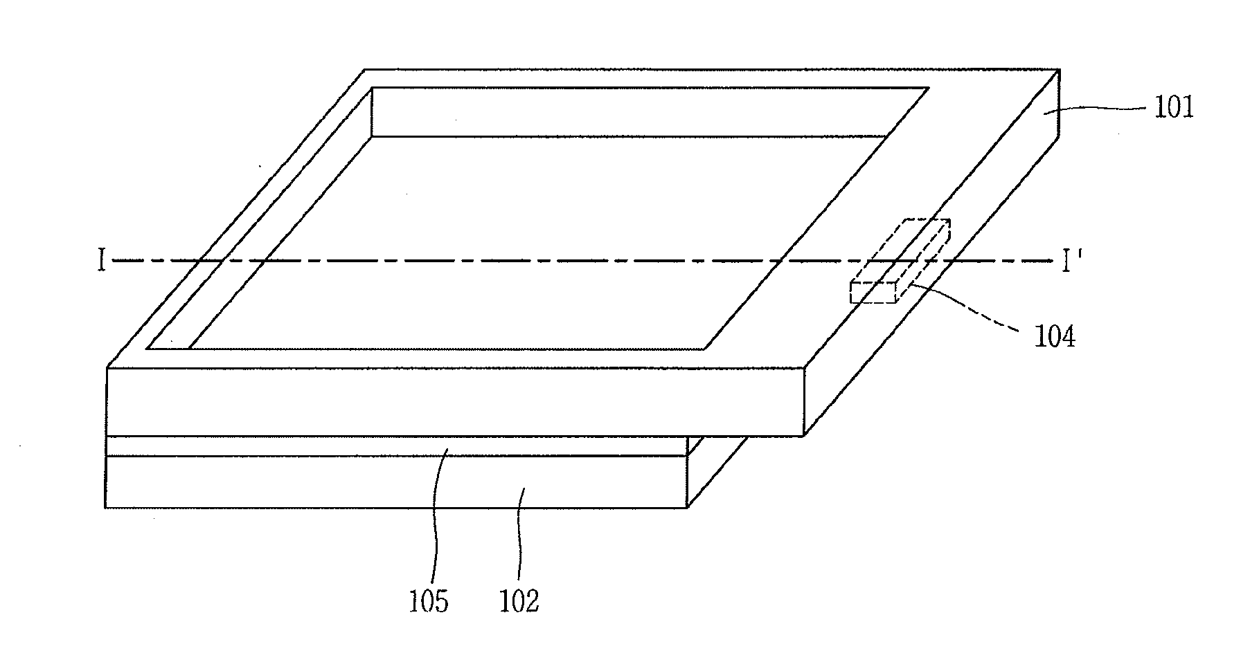
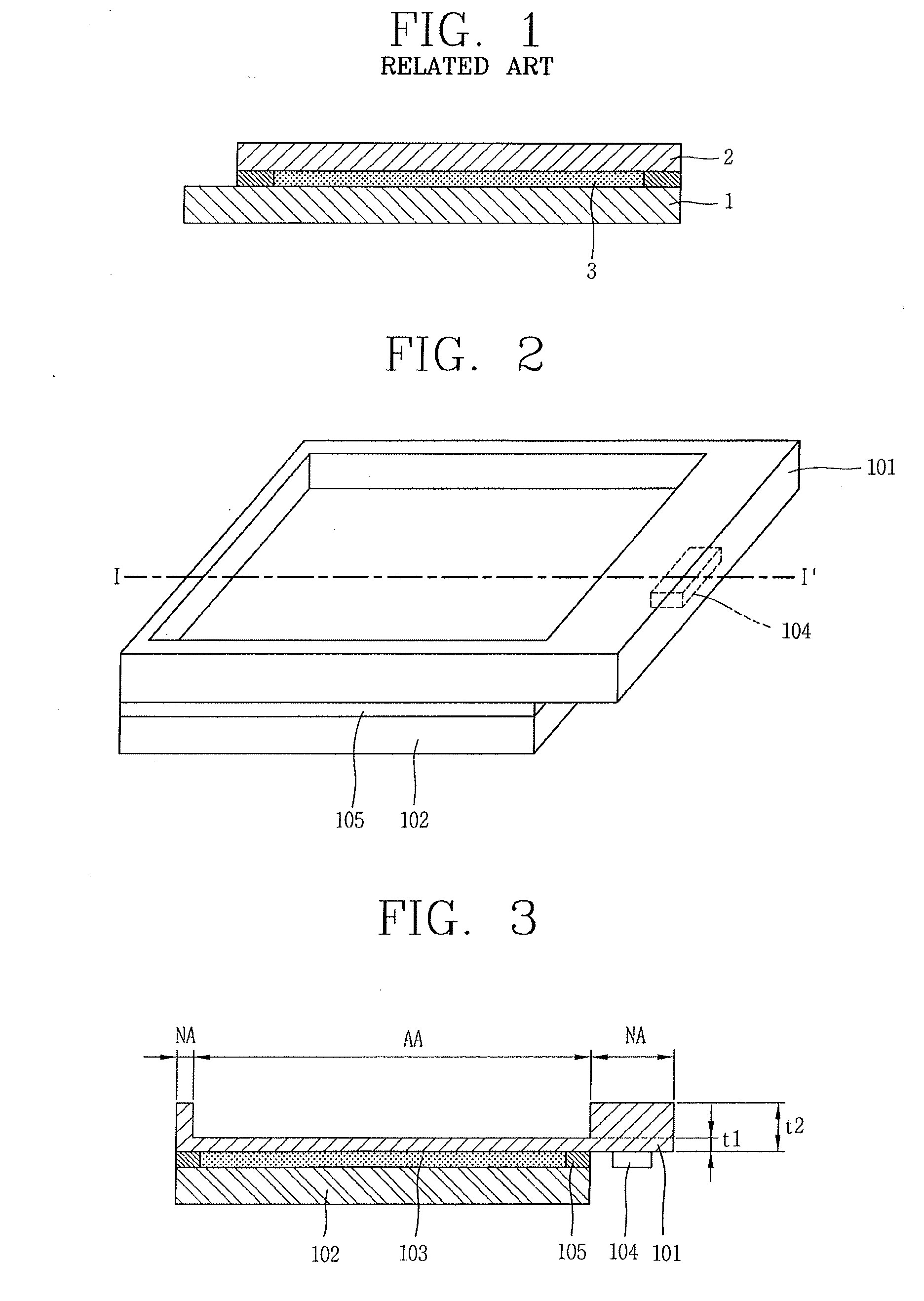
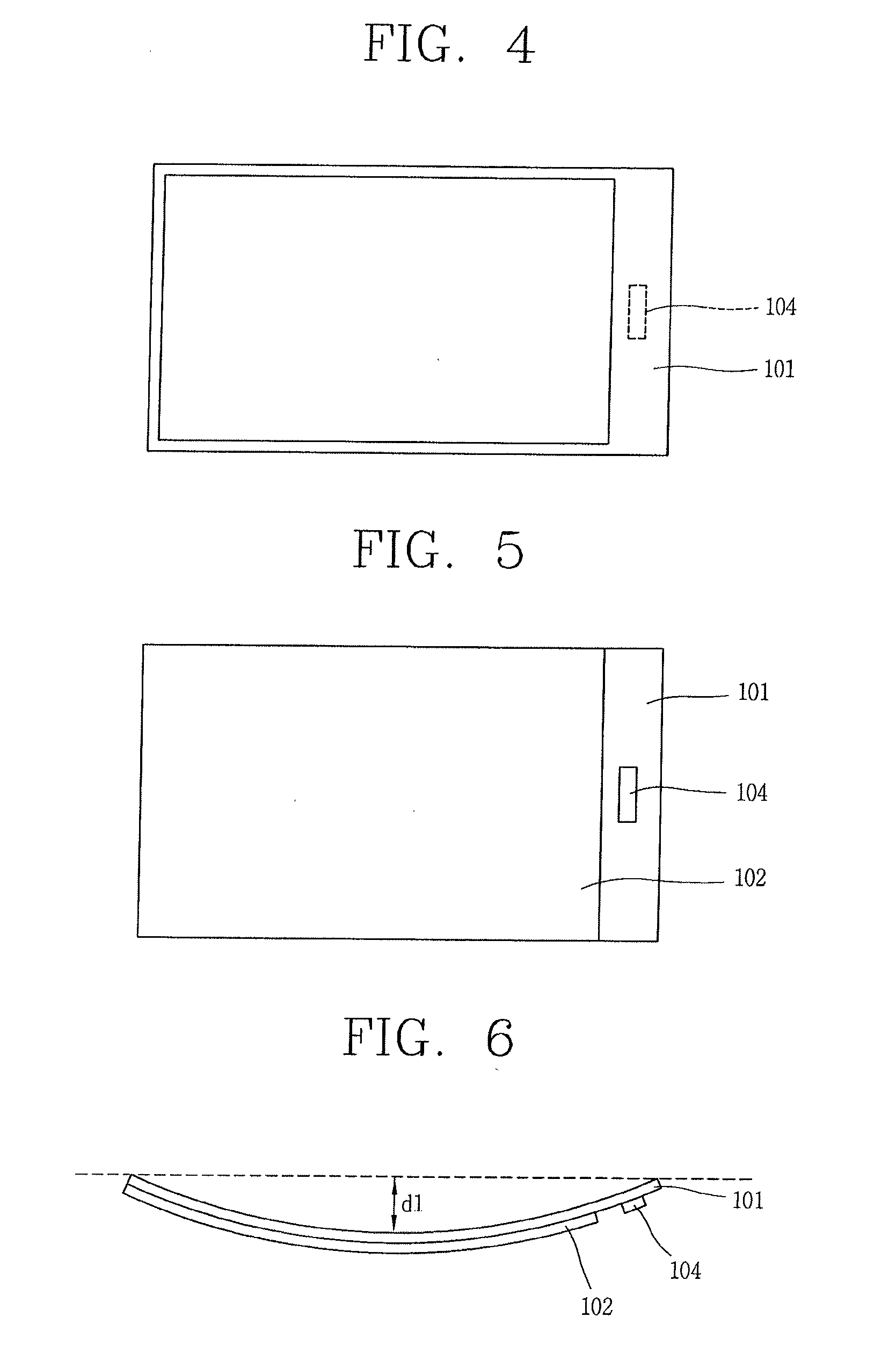
[0025]FIG. 2 is a perspective view showing a flexible display device in accordance with an exemplary embodiment, FIG. 3 is a sectional view taken along the line I-I′ of FIG. 2, FIG. 4 is a top planar view of the flexible display device of FIG. 2, FIG. 5 is a bottom planar view of the flexible display device of FIG. 2, and FIG. 6 is a side view showing a curved state of the flexible display device of FIG. 2.

[0026]Referring to FIGS. 2 to 5, a flexible display device according to an exemplary embodiment may include a glass substrate 101 having a display region AA and a non-display region NA defined on a front surface thereof, the display region AA being thinner tha...


PUM


Abstract

Disclosed is a flexible display device capable of forming a display device on a glass substrate and simultaneously ensuring flexibility, and a fabrication method thereof, the method including preparing a glass substrate having a display region and a non-display region defined on a front surface thereof, forming a display device on the display region defined on the front surface of the glass substrate, preparing a metal foil substrate, bonding the metal foil substrate to the glass substrate such that a front surface of the metal foil substrate faces the front surface of the glass substrate so as to seal the display device, attaching a first passivation film on a region of a rear surface of the glass substrate, the region corresponding to a part or all of the non-display region defined on the front surface of the glass substrate, and attaching a second passivation film on an entire rear surface of the metal foil substrate, performing a first etching with respect to the display region of the rear surface of the glass substrate by using the first passivation film as a mask, removing the first passivation film, and performing a second etching with respect to the display region and the non-display region of the rear surface of the glass substrate, removing the second passivation film, and mounting a display device driving unit on the non-display region defined on the front surface of the glass substrate.

Description

BACKGROUND[0001]1. Field of the Disclosure[0002]The present disclosure relates to a flexible display device and a fabrication method thereof, and particularly, to a flexible display device capable of forming a display device on a glass substrate and simultaneously ensuring flexibility, and a fabrication method thereof.[0003]2. Background of the Disclosure[0004]Electronic display devices are is gradually playing a more significant role these days in today's information society, and various types of electronic display devices are widely used in industrial fields and in ordinary lives.[0005]An electronic display device is usually used for a television, a computer monitor and the like. Among others, a cathode ray tube (CRT) display device, has the longest history and takes the top market share position but has many disadvantages, such as a heavy weight, a large size, a high power consumption and the like.[0006]Consequently, recently, rapid improvement of semiconductor technologies has l...

Claims


Application Information

Patent Timeline
IPC IPC(8): H05K7/00H01J9/00
CPCB32B17/061G02F1/133305G02F1/13452H05K1/0306H01L51/0097Y02E10/549H05K1/028G02F2001/133368G02F1/133368H10K77/111G02F1/1345G02F1/1333
Inventor LEE, JAE-YOUNGLEE, JUNG-HWAN
Owner LG DISPLAY CO LTD
Learn More