Print system for monitoring print jobs

Inactive Publication Date: 2011-05-26
OCE TECH
View PDF12 Cites 7 Cited by
  • Summary
  • Abstract
  • Description
  • Claims
  • Application Information

AI Technical Summary

Benefits of technology

The object of the present invention is to provide a print system that can be used efficiently and which requires a minimum of operator control t

Problems solved by technology

Prior to the receiving material being used up, a shortage thereof is in f

Method used


Image

  • Print system for monitoring print jobs
  • Print system for monitoring print jobs
  • Print system for monitoring print jobs

Examples


Embodiment Construction

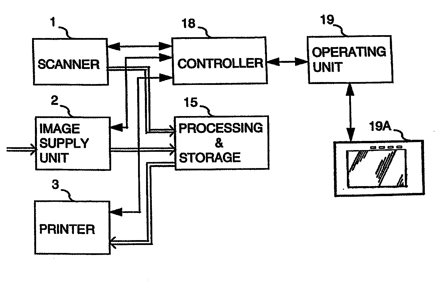
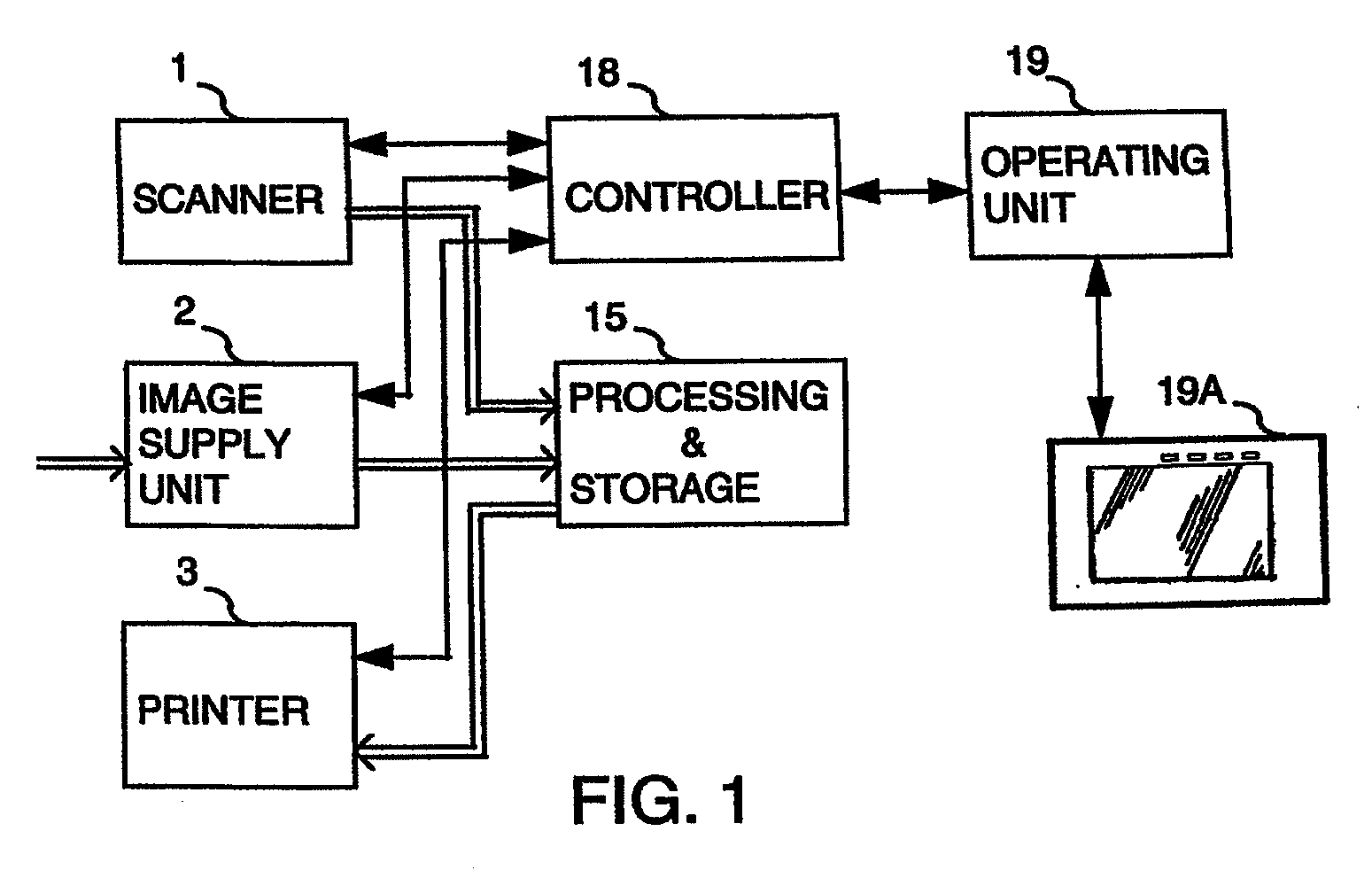
FIG. 1 shows the general arrangement of a print system. This system comprises a scanner 1 for opto-electrical scanning of a document and delivering digital image information corresponding thereto, a feeder 2 for feeding image information from an external source to the system and a print engine 3 for printing digital image information on a receiving material. Both the scanner 1 and the feeder unit 2 are connected to a device 15 for processing and intermediate storage of image information, which in turn, is connected to the print engine 3. The scanner 1, feeder unit 2, device 15 and print engine 3 are connected to a central control 18, which is also connected to an operator control unit 19 provided with an operator control panel 19A with operator control elements and a display element, in this case an LCD screen in the form of a touch screen for use by an operator at the print system. This display unit is developed further in FIG. 3A.

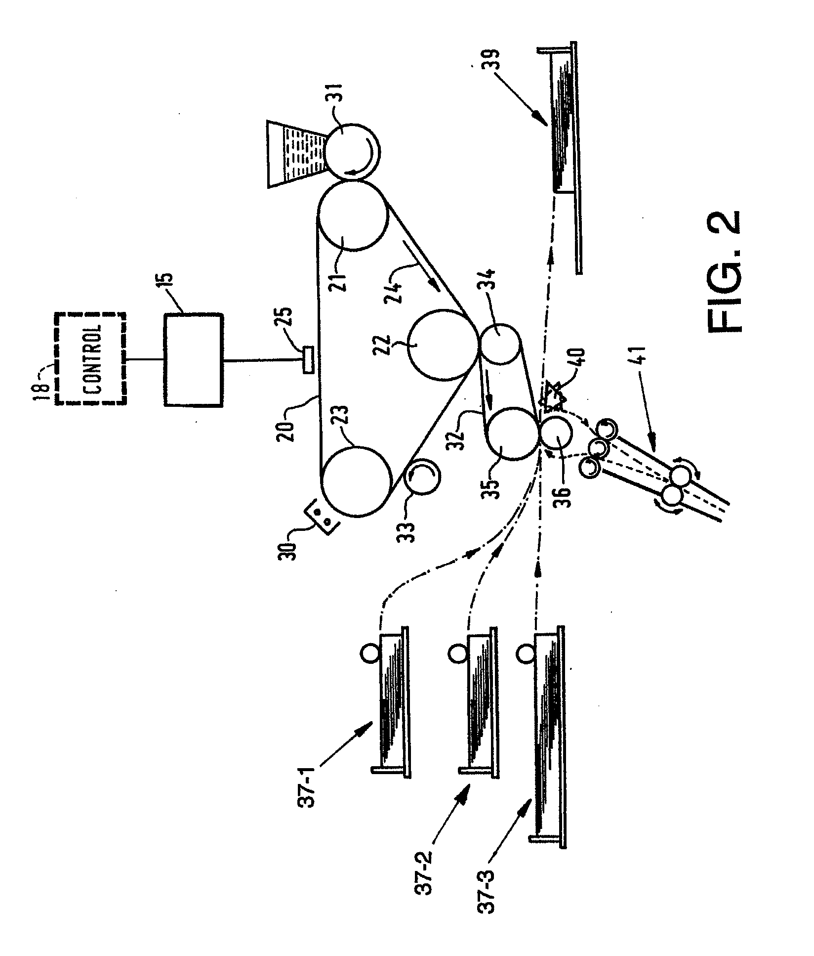
FIG. 2 shows the important parts of the print syste...


PUM


Abstract

A print system includes a print engine for printing on sheets of receiving material. A user interface unit includes a display. A plurality of holders each hold one type of receiving material and deliver the material to the print engine. A receiver receives jobs, a job being an order for printing information on sheets of receiving material of a type as specified in the order. A control system plans jobs, wherein the jobs are placed in a print queue in a sequence of finishing, the control system also being provided with a device configured to establish the types of receiving material required for printing the respective jobs in the print queue. The control system is adapted to establish, for a type of receiving material, a shortage quantity, if any, of that receiving material, for completely printing the jobs, and to indicate the shortage quantity on the display of the user interface.

Description

BACKGROUND OF THE INVENTION1. Field of the InventionThe present invention relates to a print system comprising a print engine for printing a receiving material, a plurality of holders, each for holding one type of receiving material and delivering this material to the print engine, a receiver for receiving jobs, a job being an order comprising printing information on one or more types of receiving material specified in said order, and a control system for planning jobs, by placing the jobs in a print queue in a sequence of finishing.2. Description of Background ArtA print system of this kind is known from U.S. Pat. No. 5,081,595. A job is programmed in a job program mode, a job ticket being displayed on a monitor screen. After the job has been programmed, it is moved from a memory to a print queue. The sequence of jobs in this queue is determined by priority allocated to each of the jobs and the time of arrival of the job in the queue. The print queue itself, at least the names of t...

Claims


Application Information

Patent Timeline
IPC IPC(8): G03G15/00
CPCG06K15/00G06K2215/0082H04N1/00954H04N1/00957H04N1/2307G03G15/502H04N1/2392H04N1/32635H04N1/32657H04N1/32683H04N1/2346
Inventor VAN VLIEMBERGEN, EDUARDUS J.W.BOSMA, EDWARD C.DE GROOT, RICHARD M.
Owner OCE TECH
Why Eureka
Try Eureka