Anchor bolt assembly

a technology of anchor bolts and bolts, applied in the direction of sheet joining, fastening means, mechanical equipment, etc., can solve the problems of easy loss of screws or pins, user injury, screw or pin loss, etc., and achieve the effect of convenient mounting and dismounting of plate members

Inactive Publication Date: 2011-05-26
HANWIT PRECISION IND LTD
View PDF0 Cites 17 Cited by
  • Summary
  • Abstract
  • Description
  • Claims
  • Application Information

AI Technical Summary

Benefits of technology

[0007]The present invention has been accomplished under the circumstances in view. It is one object of the present invention to provide an anchor bolt assembly, which facilitates mounting and dismounting of plate members without any tools. It is another object of the present invention to provide an anchor bolt assembly, which prevents falling of the dismounted plate member.

Problems solved by technology

However, when a user touches the thread or pointed end of a screw or pin accidentally, the user may be injured.
The screws or pins, they may be lost easily after dismounted from the plate members.
When one screw or pin is lost, the user may be unable to install the detachable plate member to the fixed plate member again.
Further, when different sizes of screws or pins are dismounted from an equipment, they may be put together, and the user shall have to spend a lot of time in picking up the correct size of screws or pins during a re-installation.
Further, mounting and dismounting a screw or pin requires the use of a hand tool.

Method used


Image

  • Anchor bolt assembly
  • Anchor bolt assembly
  • Anchor bolt assembly

Examples


Embodiment Construction

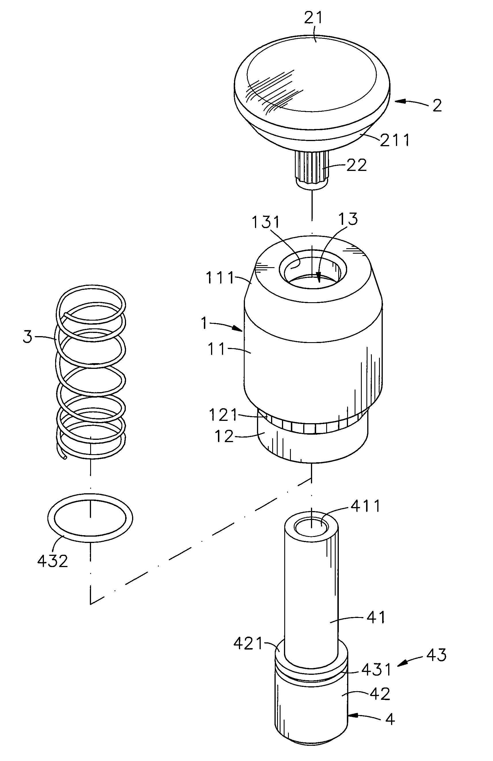
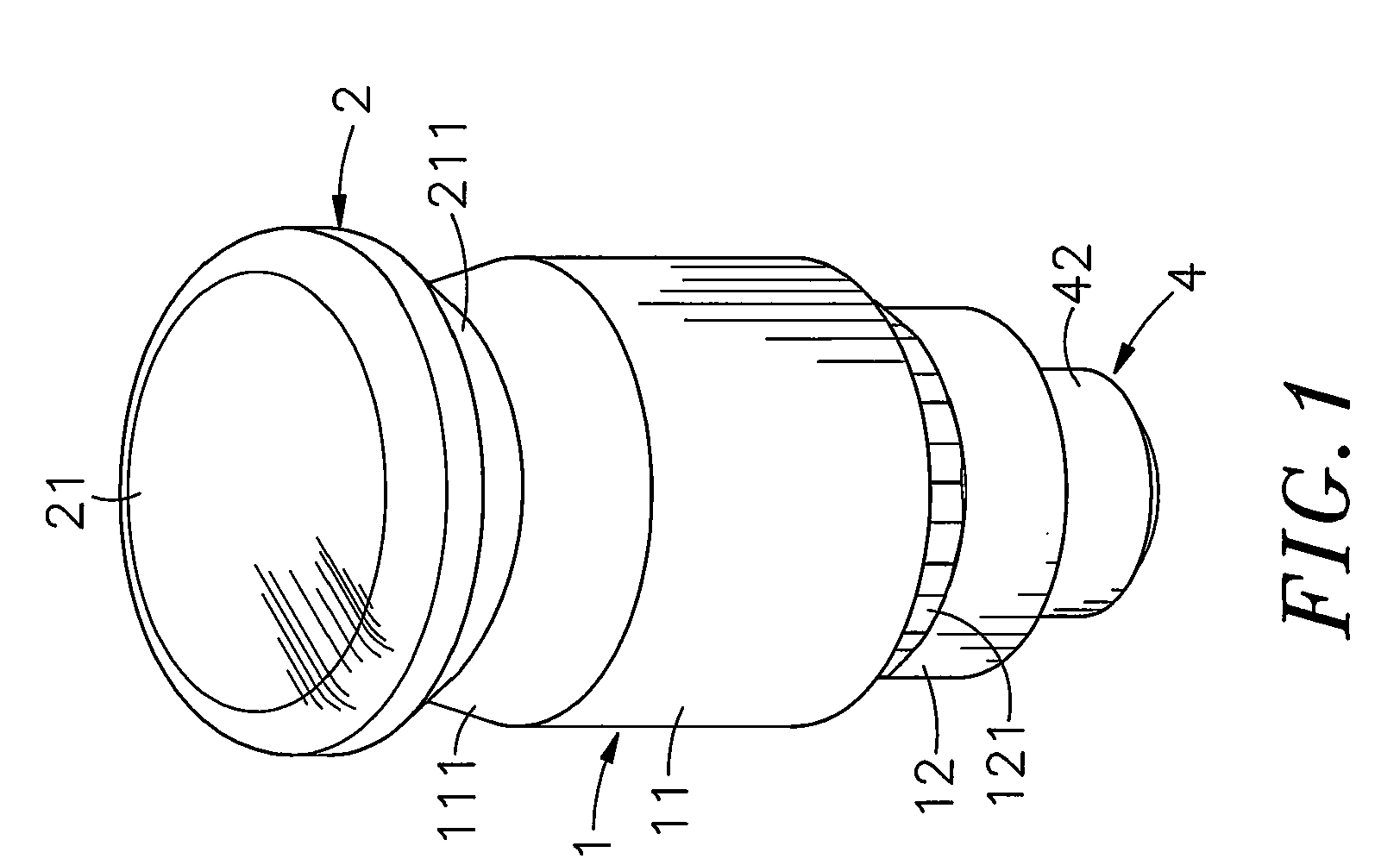
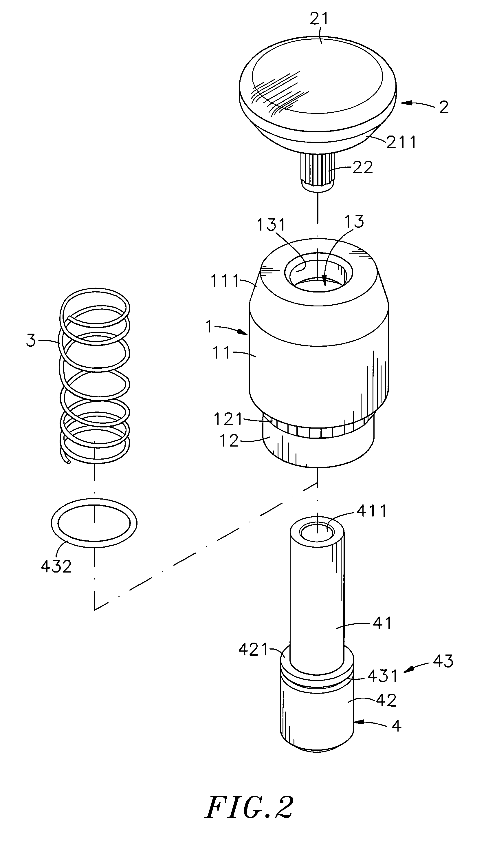
[0016]Referring to FIGS. 1-3, an anchor bolt assembly in accordance with a first embodiment of the present invention is shown comprising a sleeve 1, a pull cap 2, a spring member 3 and a retaining member 4.

[0017]The sleeve 1 comprises a tubular body 11, an anchoring portion 12 extended from one end of the tubular body 11, a plurality of locating blocks 121 arranged around the periphery of the anchoring portion 12, a chamber 13 defined in the tubular body 11, a small opening 131 formed in one end of the tubular body 11 remote from the anchoring portion 12 and disposed in communication with the chamber 13, a big opening 133 surrounded by the anchoring portion 12 and disposed in communication with the chamber 13 and in axial alignment with the small opening 131, a tapered inside wall portion 132 located on the inside between the periphery of the small opening 131 and the periphery of the chamber 13 and locating means 14 arranged around the inside wall of the chamber 13. The locating me...


PUM


Abstract

An anchor bolt assembly includes a sleeve affixed to a first plate member and having a locating groove extending around the inside wall thereof, a retaining member having a shank and a head provided with a retaining ring and movable in and out of the sleeve, a spring member adapted for forcing the retaining member out of the sleeve to a locking position to lock a second plate member to the first plate member and a pull cap connected to the distal end of the shank for pulling by the user to move the retaining member away from the locking position to an unlocking position where the second plate member is unlocked from the first plate member and the retaining ring is engaged with the locating groove to hold the retaining member in the unlocking position.

Description

BACKGROUND OF THE INVENTION[0001]1. Field of the Invention[0002]The present invention relates to anchor bolt technology and more particularly, to an anchor bolt assembly, which uses a spring member to support a retaining member in a locking position and provides a pull cap for pulling by the user to move the retaining member from the locking position to an unlocking position where a positioning means at the retaining member is engaged with a locating means inside the sleeve to keep the retaining member in the unlocking position.[0003]2. Description of the Related Art[0004]Screws or pins are commonly used many different products for the positioning of movable members. For example, a lock pin may be used to lock a sliding box or board member when the sliding rails of the sliding box or board member are moved relative to respective sliding grooves to a predetermined position. In a desk computer system, industrial computer system, work station or any other equipment where movable plate ...

Claims


Application Information

Patent Timeline
Patent Type & Authority Applications(United States)
IPC IPC(8): F16B21/00
CPCF16B5/0208
Inventor CHIU, MING-CHUNG
Owner HANWIT PRECISION IND LTD
Why Eureka
Try Eureka