Pneumatic vacuum generator

Active Publication Date: 2011-05-26
J SCHMALZ GMBH
View PDF11 Cites 57 Cited by
  • Summary
  • Abstract
  • Description
  • Claims
  • Application Information

AI Technical Summary

Benefits of technology

The present invention resolves prior art problems by providing a venturi nozzle with non-circular flow cross section. As a result, the planar venturi nozzle is compact and requires little installation space and may be constructed of multistage configuration. The flat structure of the vacuum generator

Problems solved by technology

A drawback common to all prior art vacuum

Method used


Image

  • Pneumatic vacuum generator
  • Pneumatic vacuum generator
  • Pneumatic vacuum generator

Examples


Embodiment Construction

Throughout all the figures, same or corresponding elements may generally be indicated by same reference numerals. These depicted embodiments are to be understood as illustrative of the invention and not as limiting in any way. It should also be understood that the figures are not necessarily to scale and that the embodiments are sometimes illustrated by graphic symbols, phantom lines, diagrammatic representations and fragmentary views. In certain instances, details which are not necessary for an understanding of the present invention or which render other details difficult to perceive may have been omitted.

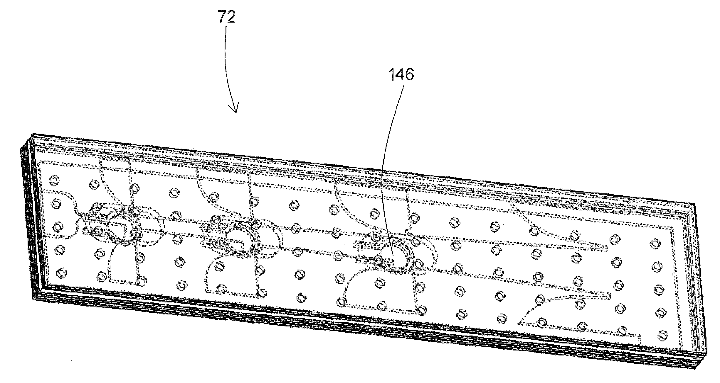
Turning now to the drawing, and in particular to FIG. 4, there is shown an exploded view of an area vacuum gripper generally designated by reference numeral 72 and having embodied therein a multistage ejector according to the present invention, generally designated by reference numeral 100. The multistage ejector 100 includes a nozzle plate 174 having planar venturi nozzles 120, 1...


PUM


Abstract

A pneumatic vacuum generator includes at least one venturi nozzle having a flow cross section which deviates for a circularity. The venturi nozzle may thus have a substantial rectangular or non-circular flow cross section like for example an oval flow cross section or an elliptical flow cross section. At least two plates are disposed in parallel relationship and joined in sandwich construction, with one of the plates constructed to accommodate the venturi nozzle.

Description

CROSS-REFERENCES TO RELATED APPLICATIONSThis application claims the priority of German Patent Application, Serial No. 10 2009 047 085.9, filed Nov. 24, 2009, pursuant to 35 U.S.C. 119(a)-(d), the content of which is incorporated herein by reference in its entirety as if fully set forth herein.BACKGROUND OF THE INVENTIONThe present invention relates to a pneumatic vacuum generator.The following discussion of related art is provided to assist the reader in understanding the advantages of the invention, and is not to be construed as an admission that this related art is prior art to this invention.Different kinds of vacuum generators are used to produce a negative pressure. In the field of automation, vacuum generators are used which generate a negative pressure using the Venturi principle. These vacuum generators are also called ejectors and require compressed air for building up the negative pressure. Prior art ejectors with cylindrical venturi nozzles or multistage ejectors with cyl...

Claims


Application Information

Patent Timeline
IPC IPC(8): F04F5/00
CPCF04F5/22F04F5/467F04F5/461F04F5/46
Inventor SCHAAF, WALTER
Owner J SCHMALZ GMBH
Why Eureka
Try Eureka