
Elastic Structure Made by Plastic Injection Molding

Inactive Publication Date: 2011-06-02
YANG TENG JEN
View PDF0 Cites 15 Cited by
  • Summary
  • Abstract
  • Description
  • Claims
  • Application Information

AI Technical Summary

Benefits of technology

[0007]The primary objective of the present invention is to provide an elastic structure made by plastic injection molding which can improve the product yield and widen the product application range.
[0011]While the connecting member is made by injection molding, the gas produced by the injection molding of the connecting member can be filled into the elastic body to make the elastic structure have elasticity to offer a buffer function. The half members are also made by injection molding, so that the shape and the thickness of the half members can be controlled by changing the mold, thus not only making the production convenient but improving the product yield and widening the application range.

Problems solved by technology

A conventional elastic structure disposed on a shoe bottom comprises plural buffer air chambers formed by blow molding to offer a buffer function, however, the buffer air chambers are formed by blow molding, the quality of the buffer air chambers depends on the air pressure which is difficult to control, so that it is unable to effectively control the size and the product yield of the buffer air chambers formed by blow molding, thus consequentially increasing the shoe cost.
In addition, the blow molding process will produce much edge waste most of which cannot be recycled, thus increasing the material cost while wasting source, which is neither environment-friendly and nor energy-saving.
Furthermore, the thickness of the buffer air chamber formed by blow molding is controlled by the air pressure, but thickness uniformity of the buffer air chamber cannot be exactly controlled, so the buffer air chamber cannot be used to control the direction of the force of the shoe, making it impossible to produce shoes for different purposes.
In addition, since the buffer air chamber is formed by blow molding, coating is the only way when it comes to putting a trademark or color on the buffer air chamber, which not only requires an extra work process but increases manufacturing cost.
In addition, the color will fade away after the buffer air chamber is used for a period of time, thus causing cost and material waste.

Method used


Image

  • Elastic Structure Made by Plastic Injection Molding
  • Elastic Structure Made by Plastic Injection Molding
  • Elastic Structure Made by Plastic Injection Molding

Examples


Embodiment Construction

[0025]The present invention will be clearer from the following description when viewed together with the accompanying drawings, which show, for purpose of illustrations only, the preferred embodiment in accordance with the present invention.

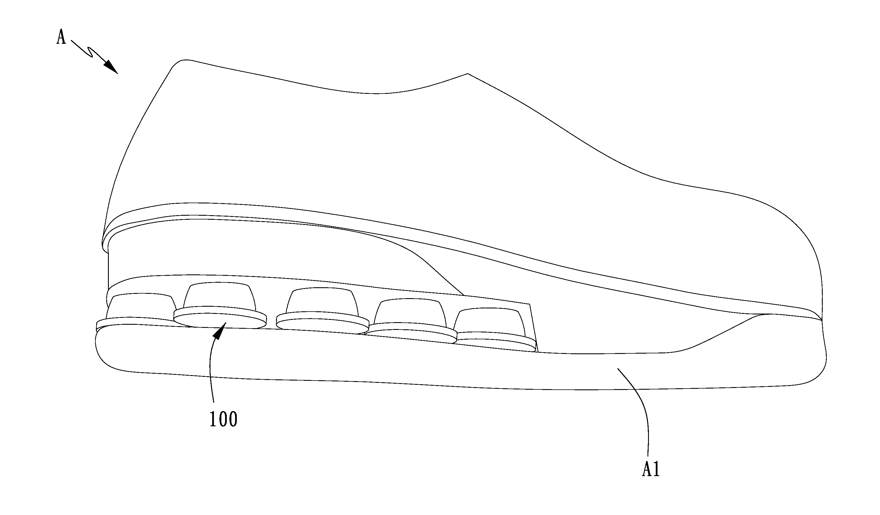
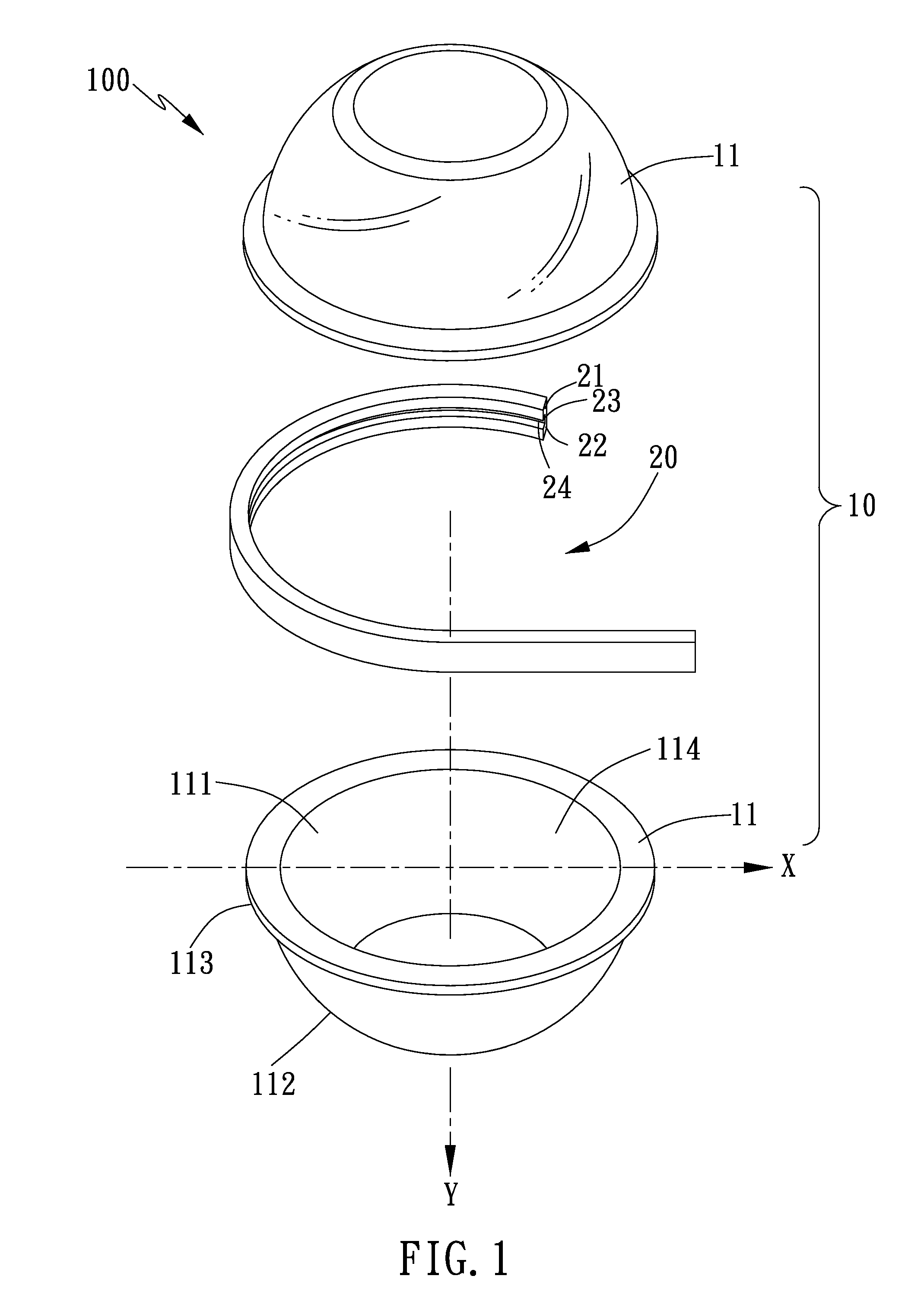
[0026]Referring to FIGS. 1-5, an elastic structure 100 in accordance with a preferred embodiment of the present invention comprises an elastic body 10 and a connecting member 20.

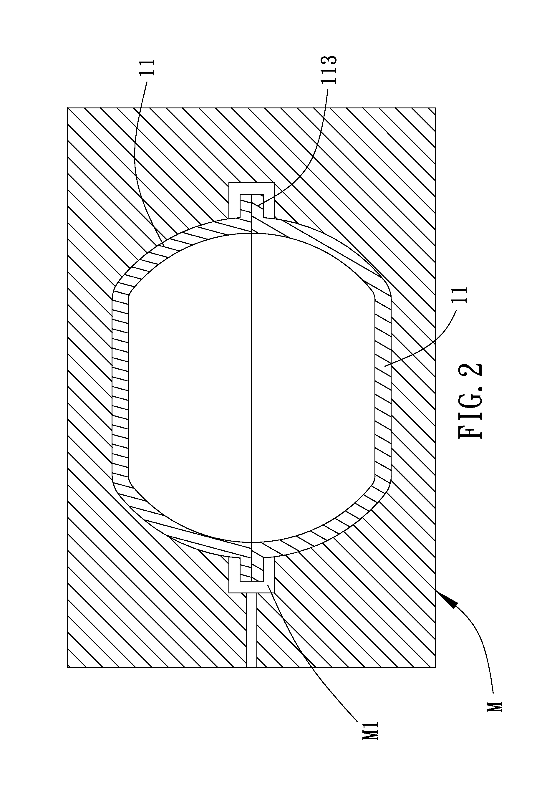
[0027]The elastic body 10 includes two oppositely-connected half members 11. Each of the half members 11 in the present embodiment is a hollow semi-spherical structure made by plastic injection molding and includes an inner surface 111, an outer surface 112, and a connecting edge 113 which is formed at a connection between the inner surface 111 and the outer surface 112 and located around a circumference of the half member 11. The connecting edge 113 extends outwards from the half member 11, and the extending direction of the connecting edge 113 is defined as a horizontal...


PUM

PropertyMeasurementUnit
Structureaaaaaaaaaa
Circumferenceaaaaaaaaaa
Elasticityaaaaaaaaaa

Abstract

An elastic structure made by plastic injection molding comprises an elastic body and a connecting member. The elastic body includes two oppositely-connected half members which are made by plastic injection molding. The connecting member is formed around the circumference of the elastic body by injection molding and seals the two half members. While the connecting member is formed by injection molding, gas will be filled into the elastic body to make the elastic body have buffer elasticity. The half members made by plastic injection molding can be changed in shape as desired by changing the mold and can be formed with a mark portion with a brand slogan or mark during the plastic injection molding, thus making the production more convenient while controlling the yield. Furthermore, the application range of the elastic structure can be widened since the elastic structure can be made into different shapes.

Description

BACKGROUND OF THE INVENTION[0001]1. Field of the Invention[0002]The present invention relates to an elastic structure, and more particularly to an elastic structure made by plastic injection molding.[0003]2. Description of the Prior Art[0004]A conventional elastic structure disposed on a shoe bottom comprises plural buffer air chambers formed by blow molding to offer a buffer function, however, the buffer air chambers are formed by blow molding, the quality of the buffer air chambers depends on the air pressure which is difficult to control, so that it is unable to effectively control the size and the product yield of the buffer air chambers formed by blow molding, thus consequentially increasing the shoe cost. In addition, the blow molding process will produce much edge waste most of which cannot be recycled, thus increasing the material cost while wasting source, which is neither environment-friendly and nor energy-saving.[0005]Furthermore, the thickness of the buffer air chamber ...

Claims


Application Information

Patent Timeline
IPC IPC(8): A43B13/20B32B37/22
CPCA43B21/28B29L2031/504B29C45/0062
Inventor YANG, TENG-JEN
Owner YANG TENG JEN
Features
  • Generate Ideas
  • Intellectual Property
  • Life Sciences
  • Materials
  • Tech Scout
  • Unparalleled Data Quality
  • Higher Quality Content
  • 60% Fewer Hallucinations
Learn More