
Ladder safety accessory kit

Active Publication Date: 2011-06-02
TRANG BRIAN T
View PDF47 Cites 38 Cited by
  • Summary
  • Abstract
  • Description
  • Claims
  • Application Information

AI Technical Summary

Benefits of technology

[0006]Another object of the present invention is to provide a ladder safety accessory kit that adjusts to compensate for uneven ground.
[0007]An even further object of the present invention is to provide a ladder safety accessory kit allows a user to quickly and easily determine a ladder is angled correctly.
[0008]Another object of the present invention is to provide a ladder safety accessory kit that allows a user to quickly and easily determine that a ladder is level.
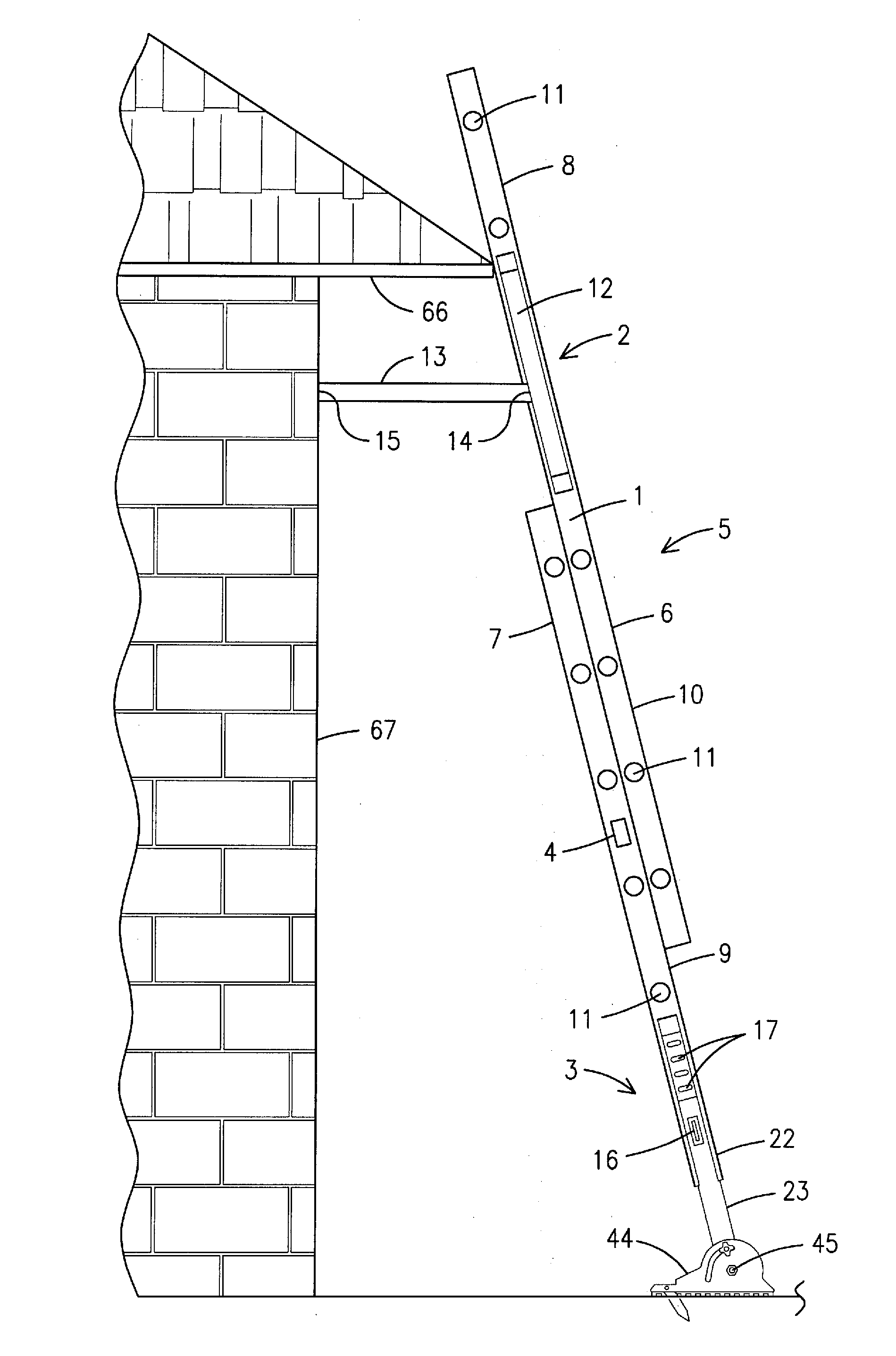
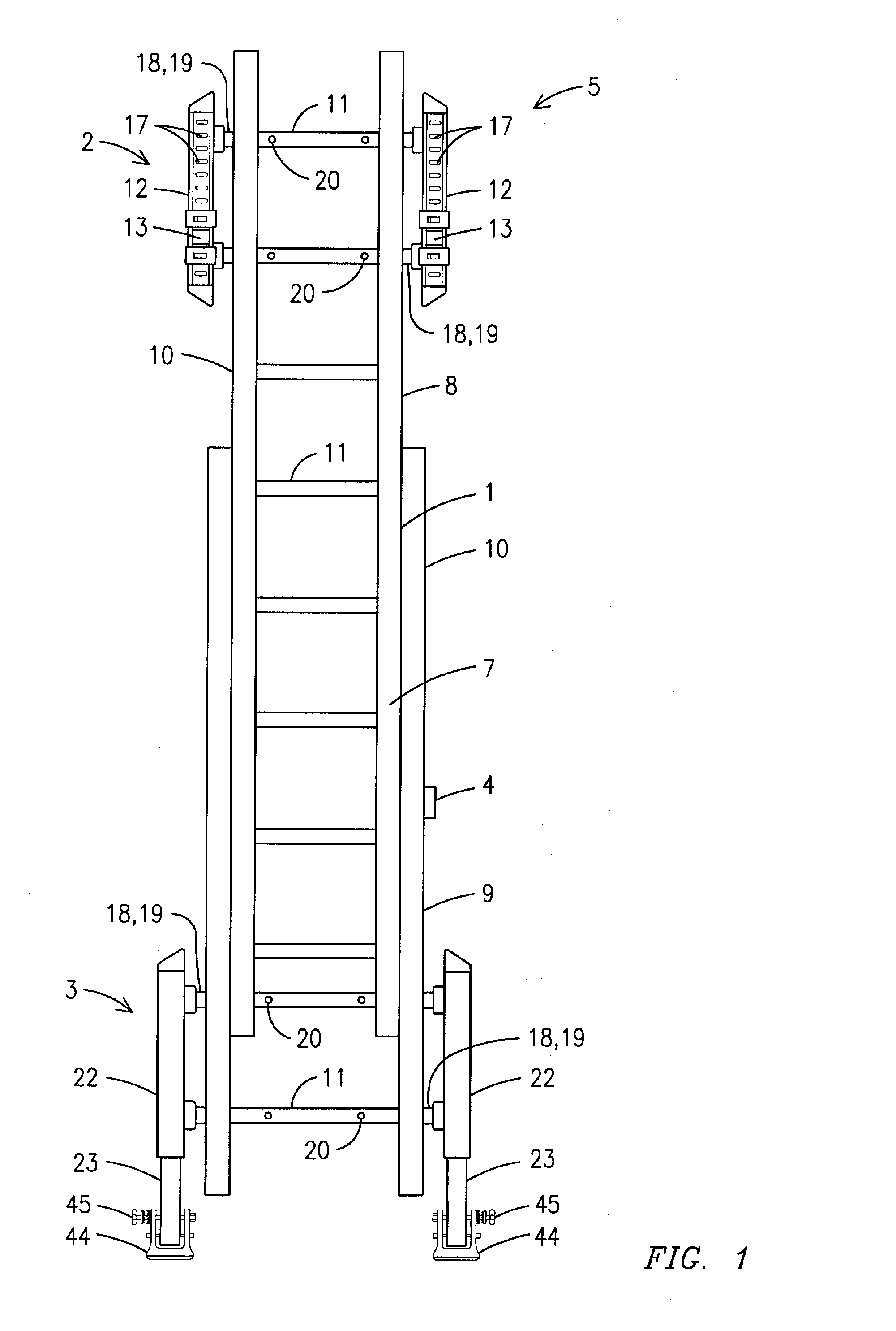
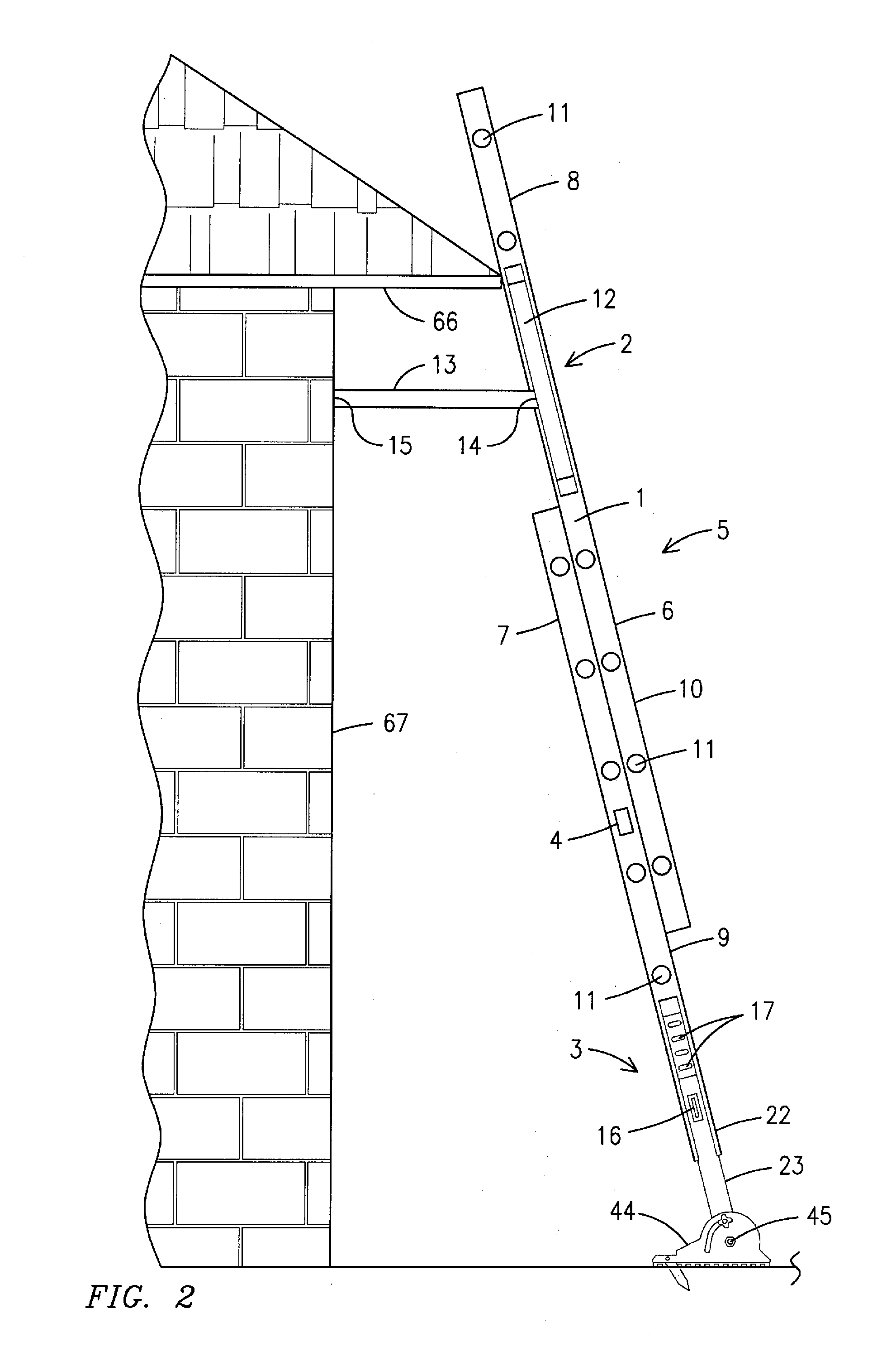
[0011]The lower stabilizer assembly is located on the lower portion of the ladder. Lower vertical adjustment bars are located on both sides of the ladder. Legs are slidably attached to the lower vertical adjustment bars, thereby allowing a user to adjust the length of the legs. Locking means engage apertures located on the lower vertical adjustment bars, thereby allowing a user to lock the legs at a desired height. The lower vertical adjustment bars may be permanently attached to the ladder via an attachment means, such as screws, nuts and bolts, welding, rivets, etc., or by other attachment means, such as one or more tubular members. One end of the at least one tubular member is permanently attached to the lower vertical adjustment bars and the opposite end placed through a hollow rung of the ladder. The tubular members may be further secured to the ladder via at least one pin, which passes through the rung of the ladder and the tubular member, and / or by a cross member that extends through the length of the rung and engages a tubular member on either side of the ladder. Feet are pivotally attached to the legs via pivot points so the ladder can be angled in relation to the feet. The feet may also be folded upward flat against the legs and lower adjustment bars for easy storage of the ladder and ladder safety accessory kit.
[0012]A bolt and locking nut assembly secures the feet to the legs and may be used to lock the ladder at a specific angle in relation to the feet, thereby ensuring that the ladder will remain in a locked position when leaned against a structure. A spike is pivotally attached to the foot via a pivot point. The spike may be folded into the foot for storage or when the foot is being used on a hard surface. The spike may also be folded into a downward position so that the spike will dig into the ground, thereby preventing the foot from sliding backwards.
[0013]The storage tray is used for holding tools and other materials while performing work on the ladder and is attached to the upper stabilizer assembly between the stabilizer bars. The storage tray may be secured to the stabilizer assembly by an attachment means, such as nuts and bolts, clips, screws, etc. Storage cups in the storage tray may be used for storing items, such as nails, screws, etc. Storage holes in the storage tray may be used for storing tools, such as screwdrivers, paintbrushes, etc. Although the storage tray may be made of any rigid material, it is preferably made of a magnetized metal that will prevent tools and other items from easily falling from the storage tray.

Problems solved by technology

The use of ladders can be very dangerous and is known to be a major cause of accidents.
However, not every structure is a flat surface and the ground is not always perfectly level.
In addition, most bases and or upper portions of most ladders are not adjustable and thus, cannot be adapted for use on a slanted ground or oddly shaped structure.
Furthermore, users currently have no way to easily determine if a ladder is horizontally level and placed at a safe angle in relation to a structure.
An even further problem with current ladders is the lack of storage space for tools and other items.
Although, many ladders do provide trays for placing tools and other items while working on the ladder, these trays are only flat surfaces that do not secure the tools and / or prevent the tools from accidentally falling to the ground.

Method used


Image

  • Ladder safety accessory kit
  • Ladder safety accessory kit
  • Ladder safety accessory kit

Examples


Embodiment Construction

[0034]For purposes of describing the preferred embodiment, the terminology used in reference to the numbered accessories in the drawings is as follows:[0035]1. ladder[0036]2. upper stabilizer assembly[0037]3. lower stabilizer assembly[0038]4. leveling measurement device[0039]5. ladder safety accessory kit[0040]6. front side[0041]7. rear side[0042]8. upper portion[0043]9. lower portion[0044]10. side[0045]11. rung[0046]12. upper vertical adjustment bar[0047]13. stabilizer bar[0048]14. proximal end of stabilizer bar[0049]15. distal end of stabilizer bar[0050]16. locking means[0051]17. aperture[0052]18. attachment means[0053]19. tubular member[0054]20. pin[0055]21. cross member[0056]22. lower vertical adjustment bar[0057]23. leg[0058]24. vertical slot[0059]25. cap[0060]26. base[0061]27. trigger[0062]28. lower lever[0063]29. upper lever[0064]30. spring[0065]31. crossbar[0066]32. cap[0067]33. extension bar[0068]34. V-shaped configuration[0069]35. horizontal extension configuration[0070]36...


PUM


Abstract

A ladder safety accessory kit (5) for strait and extension ladders (1) having an upper stabilizer assembly (2) that makes the ladder adaptable to any shaped structure or surface, a lower stabilizer assembly (3) that makes the ladder adjustable to accommodate for uneven ground, a leveling measurement device (4) that allows a user to quickly and easily determine that the ladder is level and angled correctly and a storage tray (36) that provides a storage area for tools and other items. The ladder safety accessory kit may be integrated with new ladders or used to retrofit existing ladders.

Description

BACKGROUND OF THE INVENTION[0001]This invention relates to safety devices for strait ladders and extension ladders, more particularly, a ladder safety accessory kit that levels, stabilizes and holds a ladder in place during use, thereby ensuring the safety of a user while climbing and / or performing work while on the ladder.[0002]Many jobs require the use of ladders to reach areas that are not accessible or within reach of a person standing on the ground. Ladders are commonly used to climb onto roofs of houses and other buildings. Ladders are also used to perform jobs, such as painting, washing windows and so forth. Normally, the bottom portion of the ladder rests on the ground or other similar horizontal surface and the upper end of the ladder typically leans against the vertical wall surface of a building or work surface so that the ladder is oriented at an angle which makes it easy and safe for a user to climb up and down. The use of ladders can be very dangerous and is known to b...

Claims


Application Information

Patent Timeline
IPC IPC(8): E06C7/46E06C7/14
CPCE06C7/44E06C7/48E06C7/46
Inventor TRANG, BRIAN T.
Owner TRANG BRIAN T
Learn More