Liquid ejection apparatus

Active Publication Date: 2011-06-02
BROTHER KOGYO KK
View PDF6 Cites 12 Cited by
  • Summary
  • Abstract
  • Description
  • Claims
  • Application Information

AI Technical Summary

Benefits of technology

[0007]An object of the present invention is to provide a liquid ejection apparatus which c

Problems solved by technology

However, the apparatus must be large in size when a capillary viscosity meter, a falling-ball

Method used


Image

  • Liquid ejection apparatus
  • Liquid ejection apparatus
  • Liquid ejection apparatus

Examples


Embodiment Construction

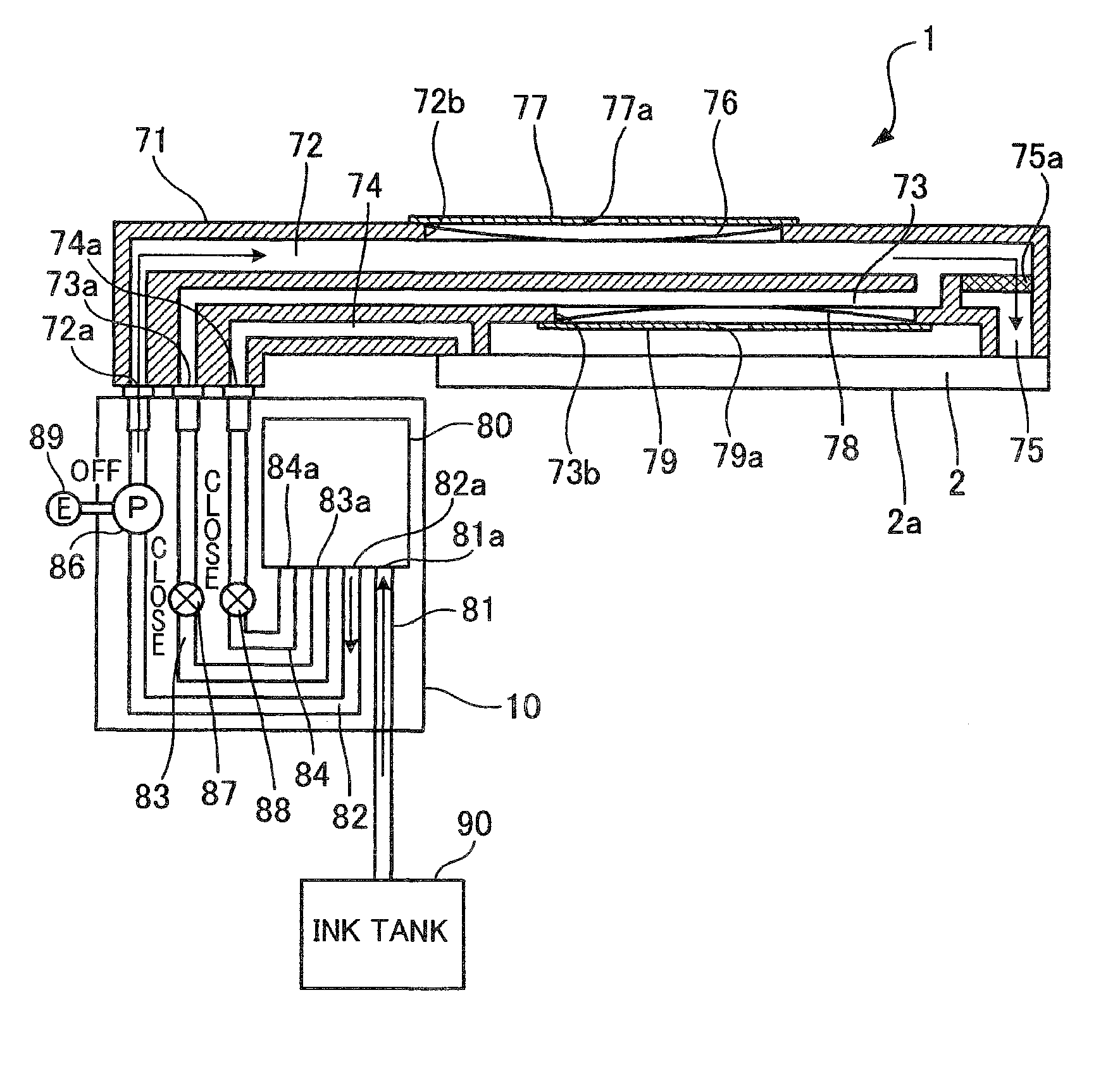
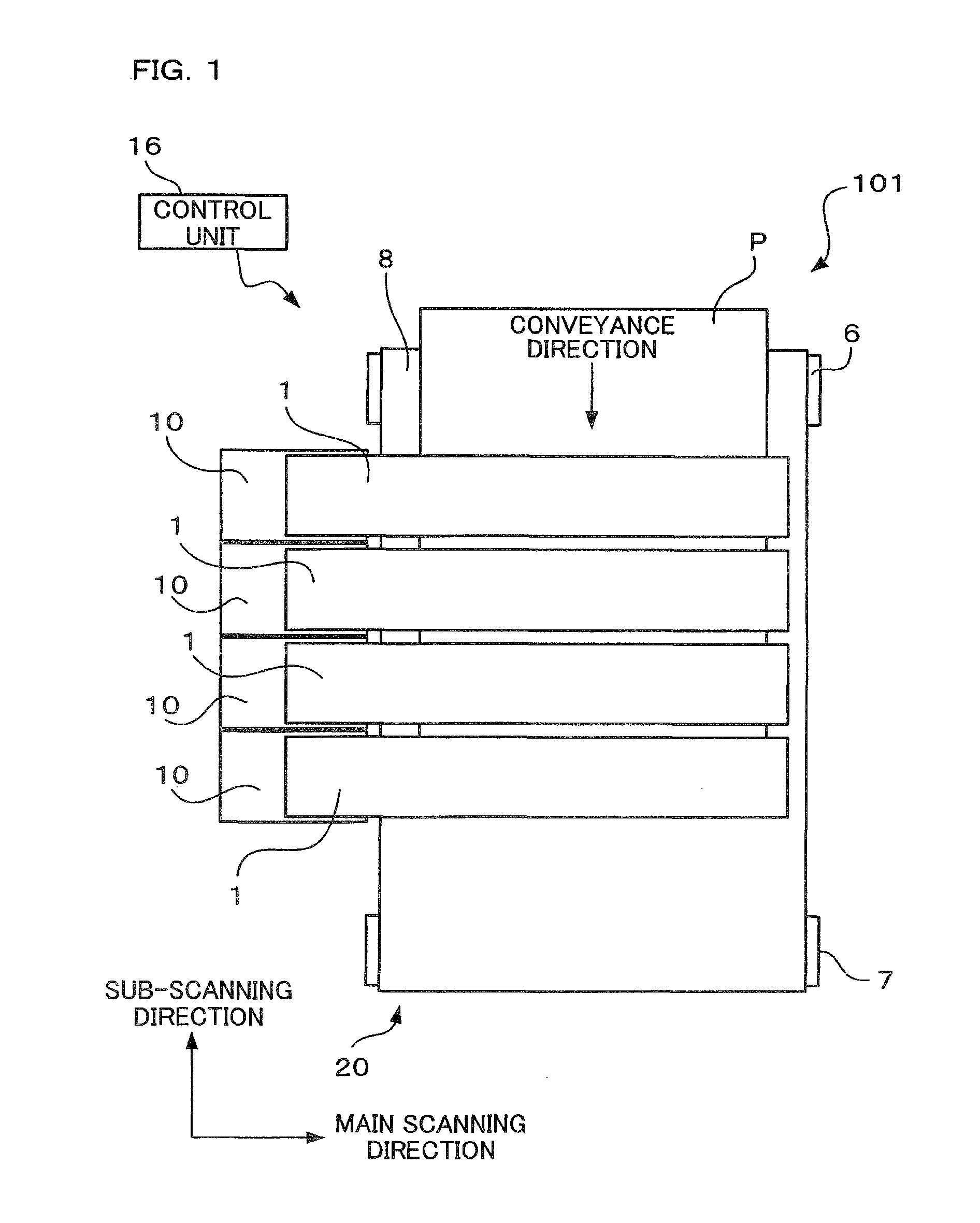
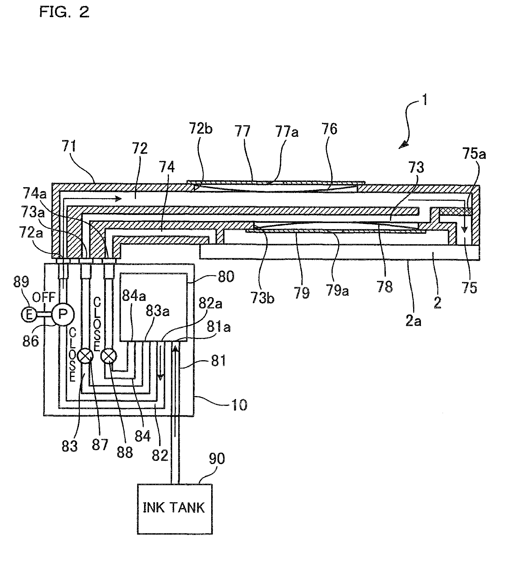
[0018]An inkjet printer 101 according to an embodiment of the present invention includes, as shown in FIG. 1, a conveying unit 20 which conveys sheets P from upward to downward in FIG. 1, four inkjet heads 1 ejecting magenta, cyan, yellow, and black ink droplets respectively onto a sheet P conveyed by the conveying unit 20, four ink supply units 10 supplying ink to the inkjet heads 1, and a control unit 16. In the present embodiment, a sub-scanning direction is in parallel to the conveyance direction of the sheets P on the conveying unit 20, whereas a main scanning direction is orthogonal to the sub-scanning direction and along the horizontal plane.

[0019]The conveying unit 20 has two belt rollers 6 and 7 and an endless conveyor belt 8 stretched between the rollers 6 and 7. The belt roller 7 is a driving roller which is rotated by a driving force from an unillustrated conveyor motor. The belt roller 6 is a driven roller which rotates as the conveyor belt 8 is moved by the rotation of...


PUM


Abstract

A liquid ejection apparatus includes a valve which adjusts the flow rate of a recording liquid in a return passage connecting an outflow opening with a tank, a pump which supplies the recording liquid from the tank to the internal passage via the supply passage, a detecting unit which detects an operating state of the pump, and a calculating unit which calculates the viscosity of the recording liquid. The calculating unit calculates the viscosity of the recording liquid based on the operating state of the pump detected by the detecting unit, while the recording liquid in the tank circulates so as to serially pass through the supply passage, the internal passage, and the return passage.

Description

[0001]The present application claims priority from Japanese Patent Application No. 2009-270529, which was filed on Nov. 27, 2009, the disclosure of which is herein incorporated by reference in its entirety.BACKGROUND OF THE INVENTION[0002]1. Field of the Invention[0003]The present invention relates to a liquid ejection apparatus having a recording liquid ejection head which ejects recording liquid from ejection openings.[0004]2. Description of the Related Art[0005]The performances regarding ink supply and ink ejection in an inkjet recording apparatus significantly depend on the viscosity of ink. There is a known recording apparatus which directly measures the ink viscosity by a viscosity meter such as capillary viscosity meter, falling-ball viscosity meter, and rotational viscosity meter is provided on an ink supply passage.SUMMARY OF THE INVENTION[0006]However, the apparatus must be large in size when a capillary viscosity meter, a falling-ball viscosity meter, or a rotational visc...

Claims


Application Information

Patent Timeline
IPC IPC(8): B41J29/38
CPCB41J2/175B41J29/38B41J2/17509
Inventor MATOBA, KENJI
Owner BROTHER KOGYO KK
Why Eureka
Try Eureka