Catheter with pressure measuring tip

a catheter and tip technology, applied in the field of catheters and probe construction, can solve problems such as unfavorable damage to heart tissue and even perforation of the heart wall

Active Publication Date: 2011-06-02
BIOSENSE WEBSTER (ISRAEL) LTD
View PDF90 Cites 285 Cited by
  • Summary
  • Abstract
  • Description
  • Claims
  • Application Information

AI Technical Summary

Problems solved by technology

Excessive pressure, however, may cause undesired damage to the heart tissue and even perforation of the heart wall.

Method used


Image

  • Catheter with pressure measuring tip
  • Catheter with pressure measuring tip
  • Catheter with pressure measuring tip

Examples


Embodiment Construction

Overview

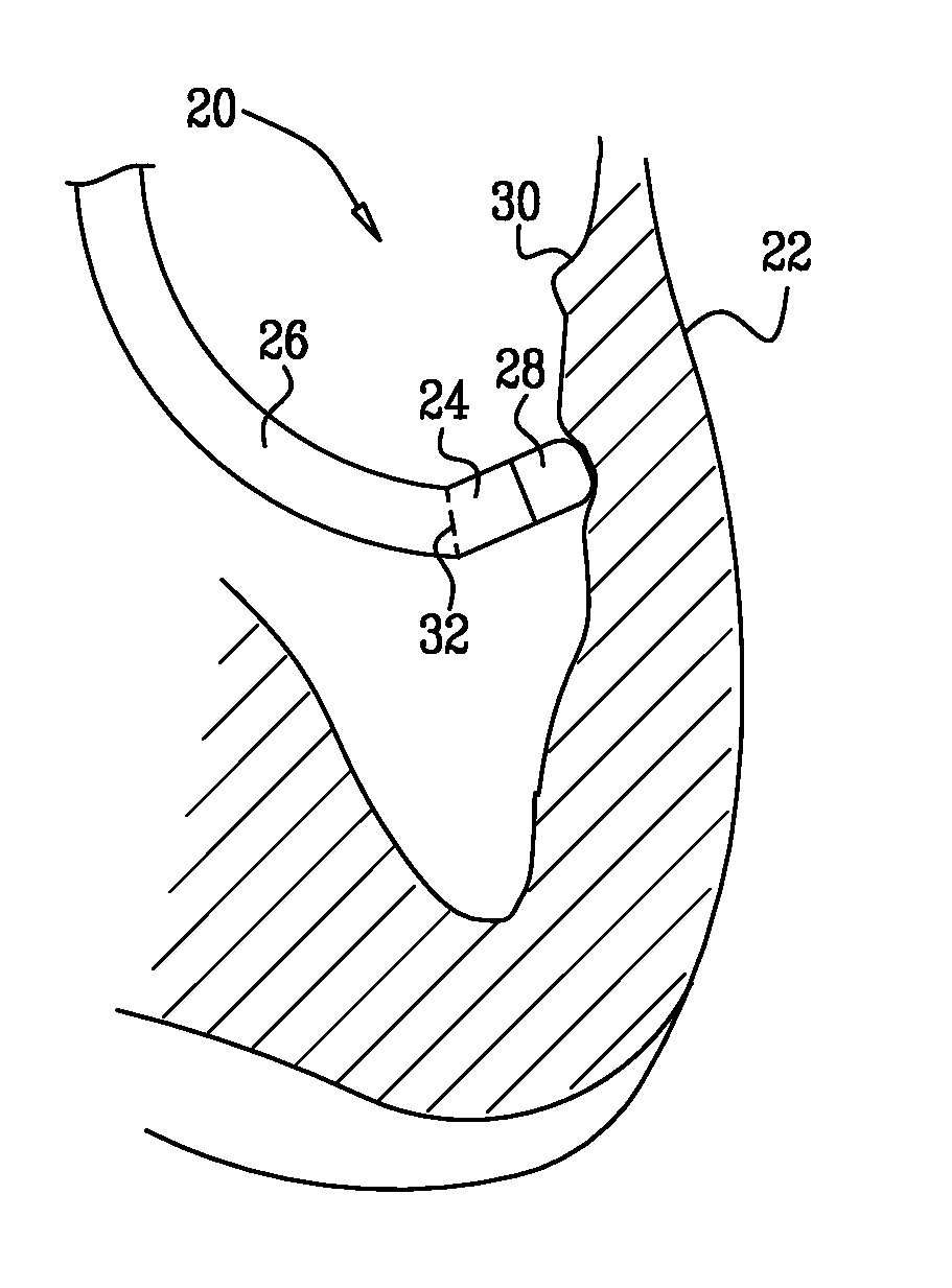
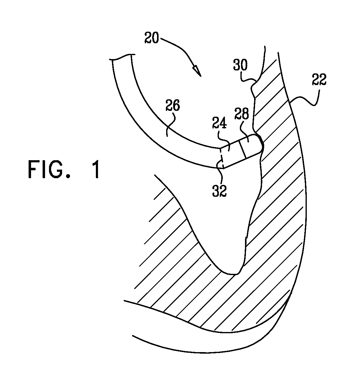
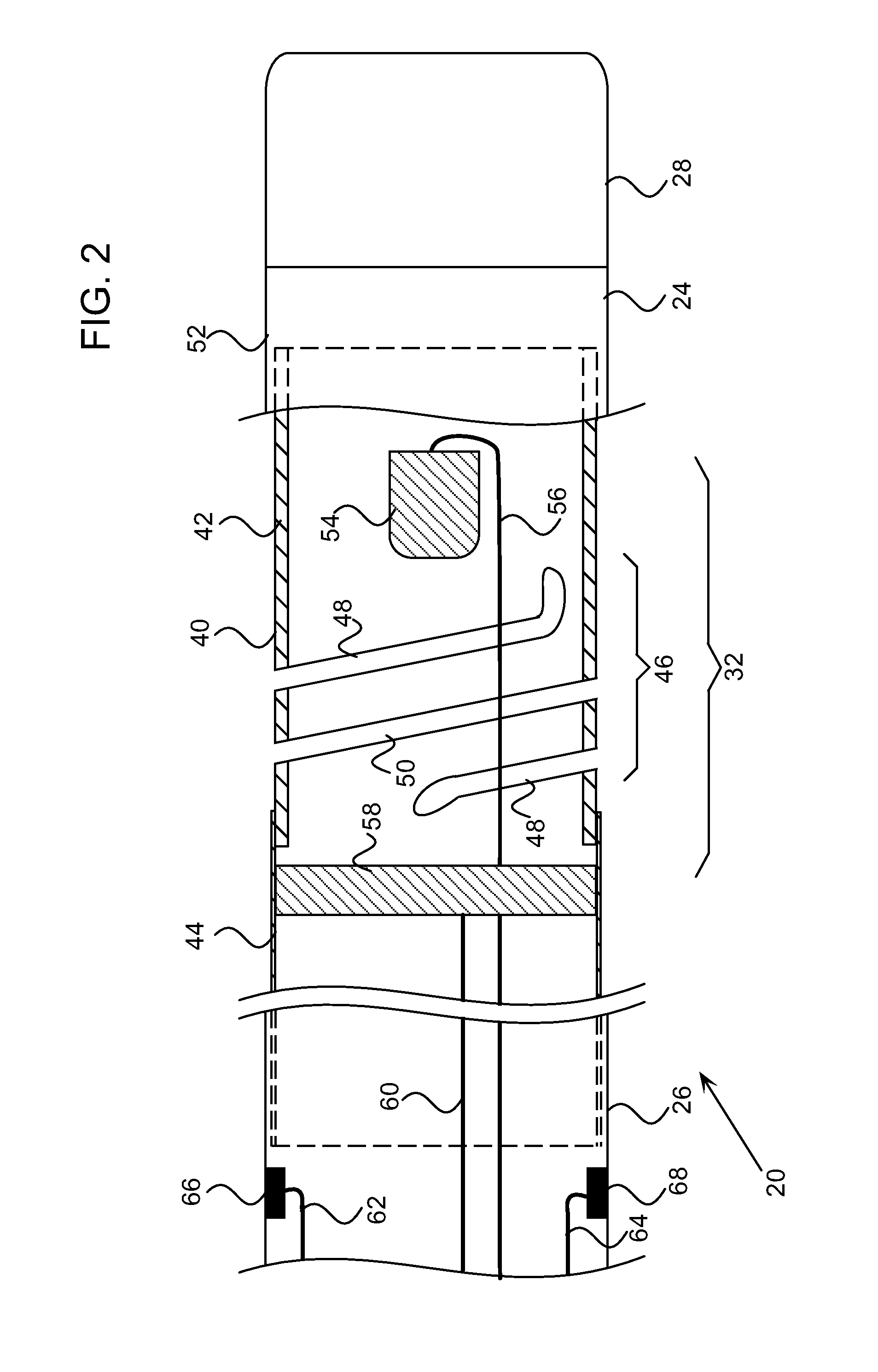
[0027]Embodiments of the present invention provide a novel design of an invasive probe, such as a catheter. The probe comprises a flexible insertion tube for insertion into a body cavity of a patient. A distal tip of the probe is coupled to the distal end of the insertion tube by a coupling member. The coupling member comprises a tubular piece of elastic material with a plurality of intertwined helices, typically a double helix, cut in a portion of the piece.

[0028]The plurality of intertwined helices permit the coupling member to bend in response to pressure exerted on the distal tip when the tip engages tissue in the body cavity. The bending is significantly greater, and is more uniform, than would be achieved by a single helix cut in the coupling member, for the same exerted pressure. The greater and more uniform bending facilitates improved measurement of the pressure causing the bending. In addition, dimensions of the helices may be chosen to significantly reduce the siz...


PUM


Abstract

A medical probe, consisting of a flexible insertion tube, having a distal end for insertion into a body cavity of a patient, and a distal tip, which is disposed at the distal end of the flexible insertion tube is configured to be brought into contact with tissue in the body cavity. The probe also includes a coupling member, which couples the distal tip to the distal end of the insertion tube and which consists of a tubular piece of an elastic material having a plurality of intertwined helical cuts therethrough along a portion of a length of the piece.

Description

FIELD OF THE INVENTION[0001]The present invention relates generally to invasive medical devices, and specifically to the construction of probes for insertion into body organs.BACKGROUND OF THE INVENTION[0002]In some diagnostic and therapeutic techniques, a catheter is inserted into a chamber of the heart and brought into contact with the inner heart wall. In such procedures, it is generally important that the distal tip of the catheter engages the endocardium with sufficient pressure to ensure good contact. Excessive pressure, however, may cause undesired damage to the heart tissue and even perforation of the heart wall.[0003]For example, in intracardiac radio-frequency (RF) ablation, a catheter having an electrode at its distal tip is inserted through the patient's vascular system into a chamber of the heart. The electrode is brought into contact with a site (or sites) on the endocardium, and RF energy is applied through the catheter to the electrode in order to ablate the heart ti...

Claims


Application Information

Patent Timeline
Patent Type & Authority Applications(United States)
IPC IPC(8): A61B5/05
CPCA61B18/1492A61B2018/00351A61M25/0069A61B2019/5251A61M25/0054A61B2019/464A61B2090/064A61B2034/2051
Inventor BEECKLER, CHRISTOPHER THOMASGOVARI, ASSAFEPHRATH, YARON
Owner BIOSENSE WEBSTER (ISRAEL) LTD
Why Eureka
Try Eureka