Acoustic attenuation panel for aircraft for engine nacelle

a technology of acoustic attenuation panel and engine, which is applied in the direction of power plant arrangement/mounting, air transportation, jet propulsion plant, etc., can solve the problems of high cost of realizing these acoustic attenuation panels, and achieve the effect of optimizing the weight and sound absorption characteristics of the panel

Inactive Publication Date: 2011-06-09
SAFRAN NACELLES
View PDF13 Cites 53 Cited by
  • Summary
  • Abstract
  • Description
  • Claims
  • Application Information

AI Technical Summary

Benefits of technology

[0029]This more particular aim of the invention is achieved with a panel according to the preceding, wherein the porous material includes cavities: th

Problems solved by technology

The realization of these acoustic attenuation panels is costly in particular due to the presence of the cel

Method used


Image

  • Acoustic attenuation panel for aircraft for engine nacelle
  • Acoustic attenuation panel for aircraft for engine nacelle
  • Acoustic attenuation panel for aircraft for engine nacelle

Examples


Embodiment Construction

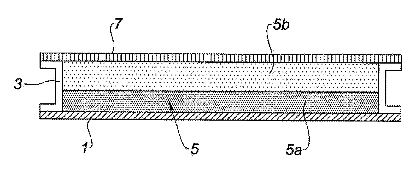
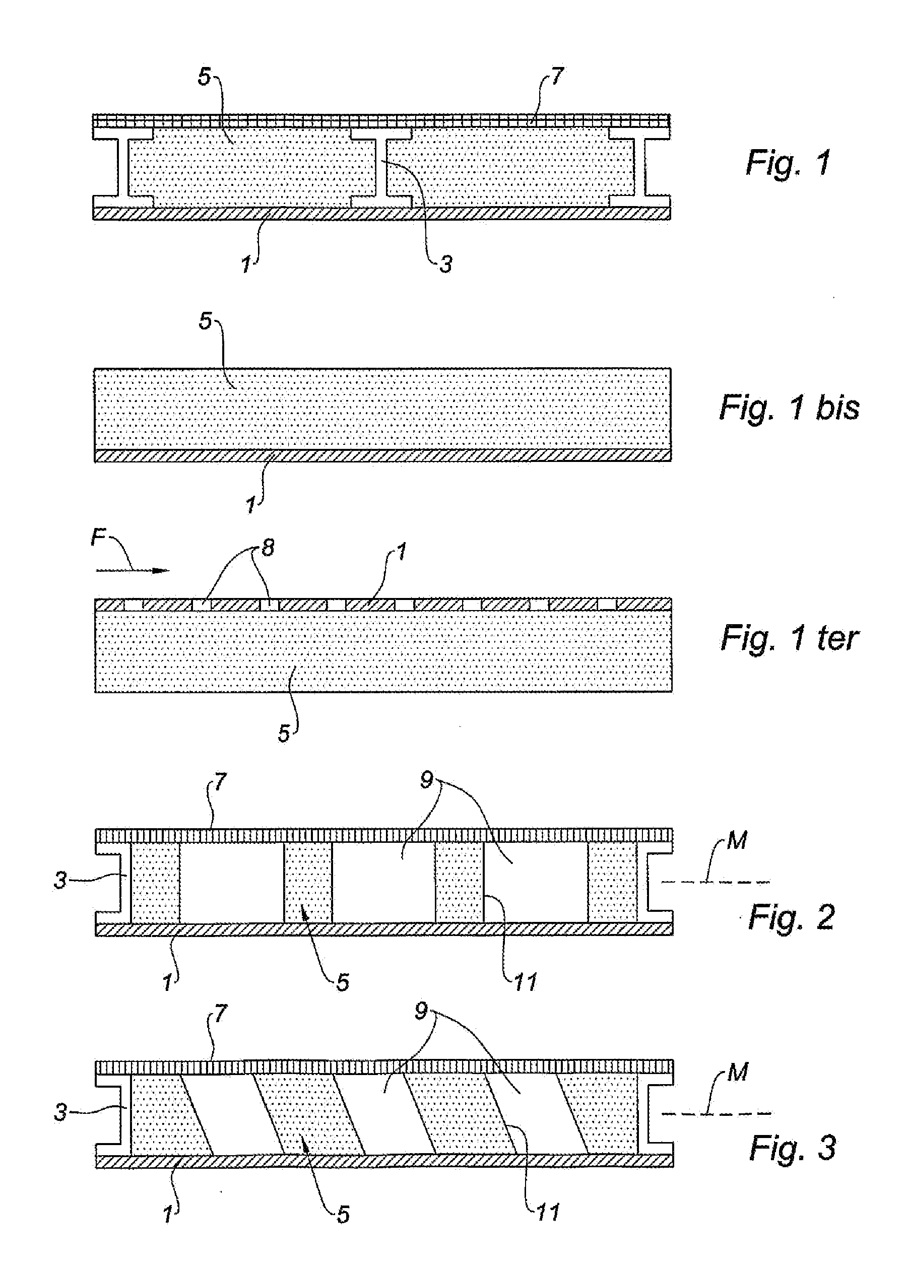
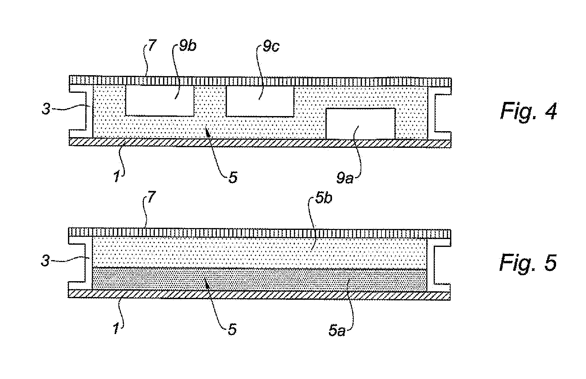
[0062]As shown in FIG. 1, an acoustic panel according to the invention includes, on the side opposite the origin of the sound excitation, a structuring skin 1, formed in a sheet.

[0063]On this structuring skin 1, a plurality of stiffeners 3 are attached that can for example be formed by beams having an i-shaped section, arranged parallel to each other.

[0064]Arranged between these stiffeners 3 is a porous material 5, i.e. a material having an open structure, i.e. open cells, able to absorb the energy from the acoustic waves.

[0065]This porous material, which can assume the form of a foam, or an expanded form, or the form of felt, or the form of an aggregate of small elements such as beads, can be fixed by adhesion or brazing on the structuring skin 1.

[0066]A resistive layer 7, formed by a perforated sheet or by a wire mesh, or by a combination of both elements, can be attached on the stiffeners 3, so as to encapsulate the porous material 5.

[0067]The stiffeners 3 can be fastened on the ...


PUM

PropertyMeasurementUnit
Temperatureaaaaaaaaaa

Abstract

This acoustic attenuation panel for an aircraft engine nacelle comprises a structuring skin (1) and, by way of acoustic absorption material, a porous material (5) attached to this skin (1).

Description

TECHNICAL FIELD[0001]The present invention concerns an acoustic attenuation panel for an aircraft engine nacelle, and nacelle elements equipped with such a panel.BACKGROUND[0002]The use of acoustic attenuation panels in aircraft engine nacelles to reduce noise emissions from turbojet engines is known from the prior art.[0003]These acoustic attenuation panels generally have a sandwich structure comprising a structuring skin, a cellular honeycomb-type structure, and a resistive layer generally formed by a perforated skin.[0004]The realization of these acoustic attenuation panels is costly in particular due to the presence of the cellular structure, and of the need to fasten said cellular structure on the structuring and perforated skins.BRIEF SUMMARY[0005]The present invention thus aims in particular to provide an acoustic attenuation skin with a simplified design in relation to the state of the art, that can be manufactured at a lower cost.[0006]This aim of the invention is achieved ...

Claims


Application Information

Patent Timeline
IPC IPC(8): B64C1/40B64D33/02B64D15/16
CPCB64D33/02B64D2033/0206B64D2033/0233B64D2033/0286F02C7/045F05D2300/612F02C7/24F02K1/827Y02T50/672F05D2300/224F02C7/047Y02T50/60
Inventor VAUCHEL, GUY BERNARDRUCKERT, GUILLAUME
Owner SAFRAN NACELLES
Why Eureka
Try Eureka