Wireless Patient Monitoring System

Inactive Publication Date: 2011-06-09
DIRECT SUPPLY
View PDF4 Cites 34 Cited by
  • Summary
  • Abstract
  • Description
  • Claims
  • Application Information

AI Technical Summary

Benefits of technology

[0004]The present invention provides a wireless sensing system that greatly simplifies programming the central monitoring unit by logically collecting signals from sensors in a given room at an associated room unit. The room unit may then forward the signals to the central monitoring unit which m

Problems solved by technology

The room unit may be powered by line power and, by locally boosting the signal from the sensors, may

Method used


Image

  • Wireless Patient Monitoring System
  • Wireless Patient Monitoring System
  • Wireless Patient Monitoring System

Examples


Embodiment Construction

Components of the Wireless Monitor System

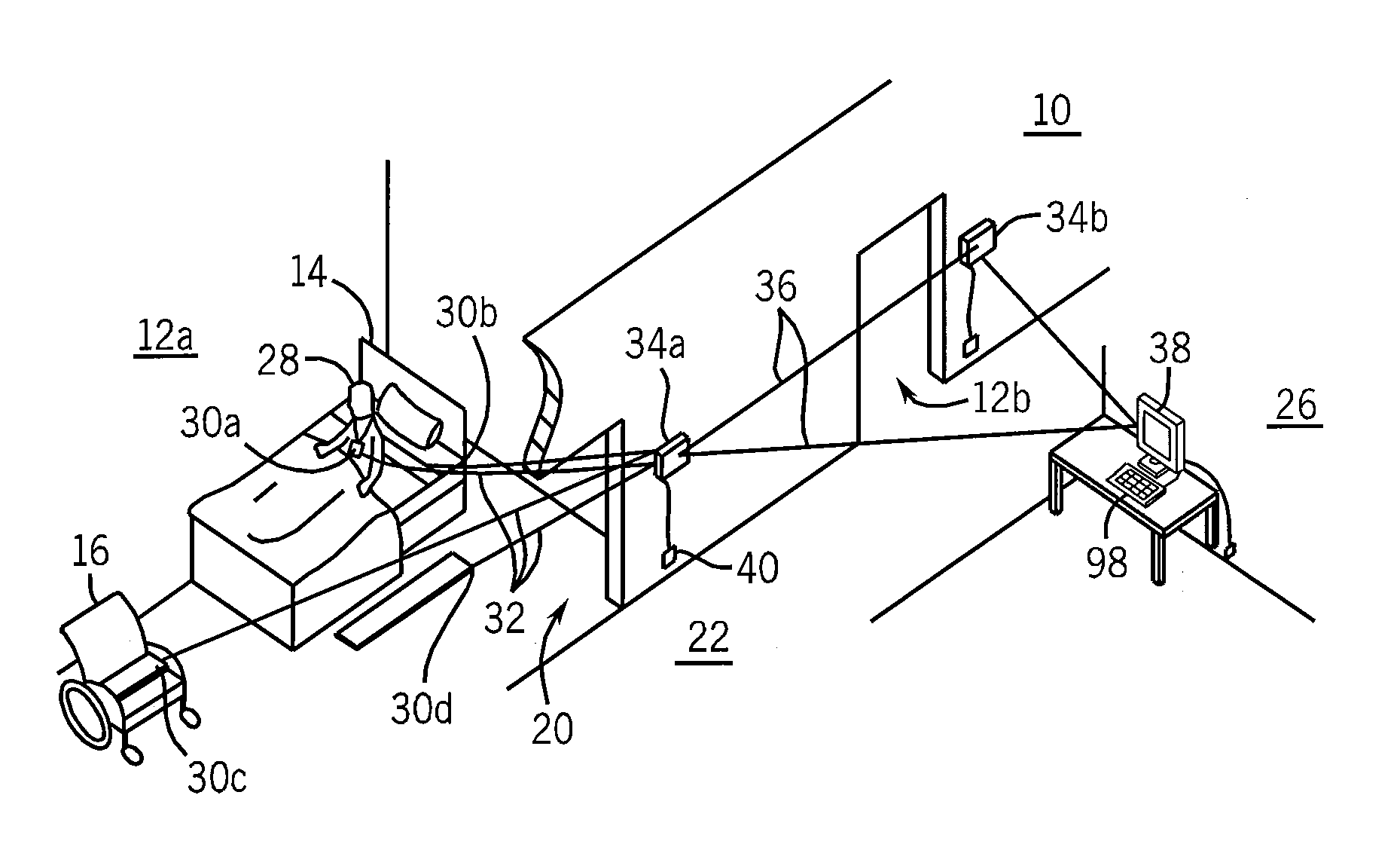
[0049]Referring now to FIG. 1, a long term care or other facility 10 suitable for use with the present invention may provide for a patient room 12a, for example, holding a patient bed 14, a chair 16, and communicating through a door 20 with a hallway 22 leading past other rooms 12b and a central monitoring area 26.

[0050]A patient 28 in the room 12a may be monitored with a set of different sensor units 30a-30d used alone or alternatively. In this example, sensor unit 30a is a patient call button on a lanyard about the patient 28. Sensor unit 30b may be associated with a bed pressure pad indicating whether the patient 28 is lying in the bed 14 or has risen. Sensor unit 30d may be associated, for example, with a floor pad positioned to activate when the patient 28 steps down out of the bed 14. The sensor unit 30c may be associated with a chair pad providing a similar function as the bed pad associated with sensor unit 30b but for a chair.

[0051]A...


PUM


Abstract

A wireless patient monitoring system employs room units to collect and display information from a variety of room based sensors, the latter of which may be battery-powered and have low range. The room units may relay collected data from the associated sensor units and, as identified to the room unit, to a central controller.

Description

BACKGROUND OF THE INVENTION[0001]Hospital and residential care facilities may provide nurse call systems allowing patients, residents, and / or caregivers (henceforth the system and method will reference actions made by the patient, although one of ordinary skill in the art should recognize that the actions and / or description may apply to any person) to request assistance at times between regularly scheduled rounds. For patients, who may need additional assistance in caring for themselves, the nurse call systems may be augmented with sensing systems that, for instance, indicate that a patient has moved from a chair or bed and thus may need assistance or monitoring. Such systems may, for example, use pressure pads placed in a bed or a chair to indicate that the occupant has risen or similar pads used as floor mats near a bed to detect that the occupant has stepped down onto the floor. Such pads incorporate switches to provide an electrical signal when activated. Tether systems that cli...

Claims


Application Information

Patent Timeline
IPC IPC(8): G08B23/00
CPCA61B5/1113A61B5/6831A61B5/6889A61B2562/08A61B5/7475A61B2560/0209A61B5/6894
Inventor BELTMANN, MARCJOHANSEN, BRAD
Owner DIRECT SUPPLY
Why Eureka
Try Eureka