Apparatus and method of classifying movement of objects in a monitoring zone

Active Publication Date: 2011-06-09
NORTECH INT
View PDF4 Cites 49 Cited by
  • Summary
  • Abstract
  • Description
  • Claims
  • Application Information

AI Technical Summary

Benefits of technology

[0015]Hence, the system according to invention does not attempt to identify each unique object in the field of view but analyses an event and by comparing this to previous knowledge of event features it is able to give a count figure using the classifier, which may comprise a neural network. The image processing is relative

Problems solved by technology

This apparatus and method may not be suitable for some applications.
This housing may be too large to fit into available space therefor and/or may not be aesthetically acceptable in certain applications.
Furthermore, it is labour, time and cost intensive to mount this apparatus on either side of the passage and it often is necessary to chase into the side-walls of the passage to install cabling extending to the apparatus.
Still furthermore, the beam projecting means on the one side and the detectors on the other side may become misaligned, which would cause the apparatus to cease functioning.
Another problem with this side-on mounted apparatus is that a person or object stationary in the passage could interrupt the beams and hence cause at least temporary insensitivity of the apparatus to other o

Method used


Image

  • Apparatus and method of classifying movement of objects in a monitoring zone
  • Apparatus and method of classifying movement of objects in a monitoring zone
  • Apparatus and method of classifying movement of objects in a monitoring zone

Examples


Embodiment Construction

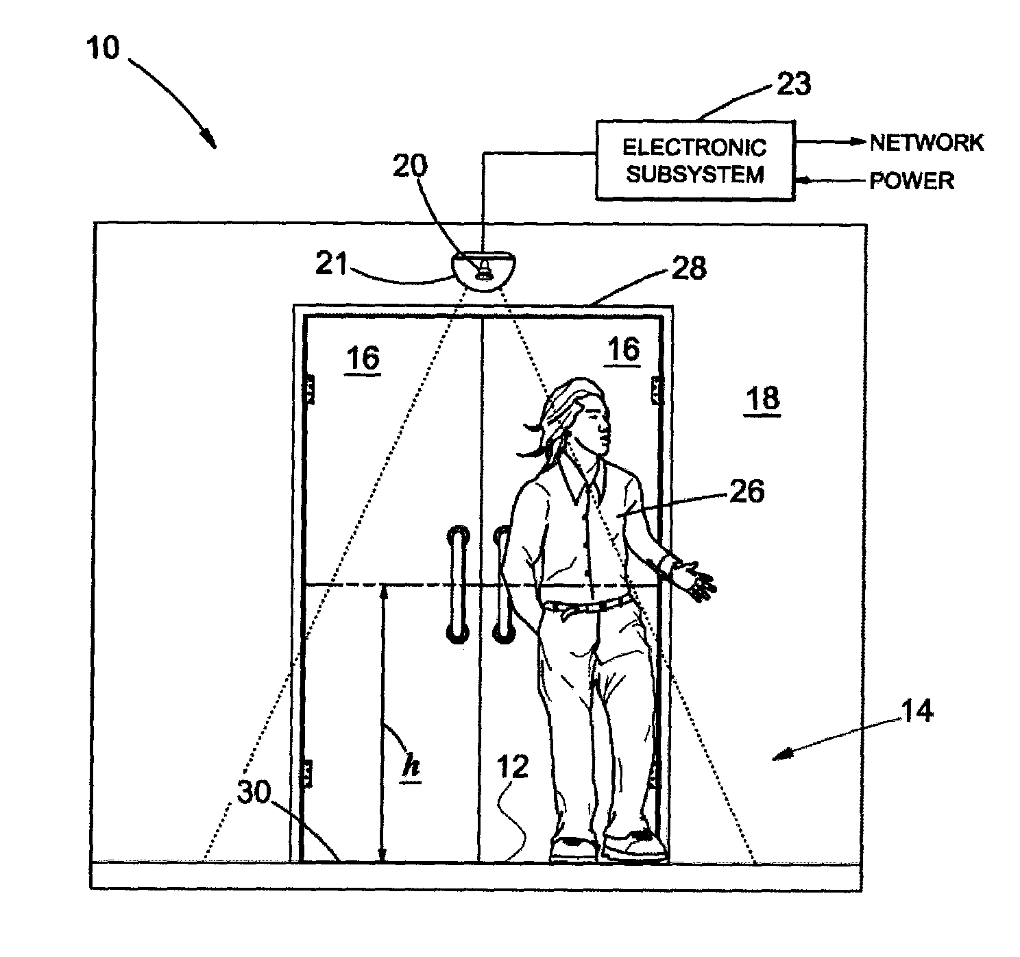
[0052]Apparatus for monitoring movement of objects through a monitoring region 12 is generally designated by reference numeral 10 in FIGS. 1 and 2.

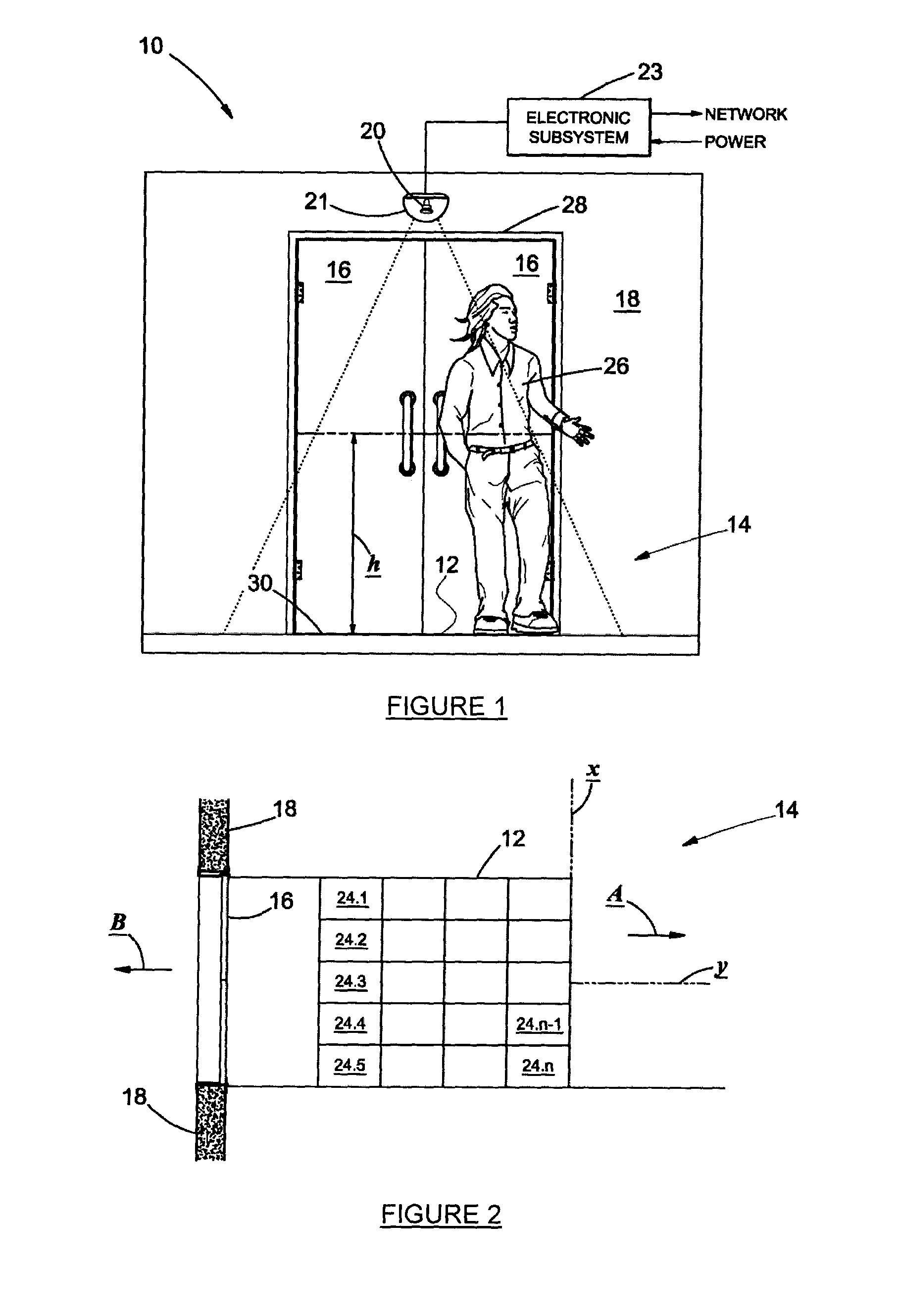
[0053]The region 12 may form part of a portal or passage 14 at a counting point, such as an entrance 16 to a building 18 and the apparatus 10 may be deployed automatically and over a period of time to monitor and count people 26 entering and leaving the building through that entrance, as will hereinafter be described.

[0054]The apparatus 10 comprises a sensing arrangement 20 sensitive to the presence or absence of an object 26 in each of a plurality of adjacent zones 24.1 to 24.n in the region. Referring to FIG. 2, the zones 24.1 to 24.n are arranged such that there are at least two adjacent rows of zones in a first direction y (that is a general direction of flow of objects through the region) and at least two adjacent rows of zones in a direction x perpendicular to the first direction. Each zone 24.1 to 24.n is associated with a respecti...


PUM


Abstract

Apparatus for monitoring movement of objects (26) through a monitoring region (12) comprises an overhead camera (20) sensitive to the presence or absence of an object (26) in each of a plurality of adjacent zones (24.1 to 24.n) in the region individually. The zones are arranged such that there are at least two adjacent rows of zones in a first direction (y) and at least two adjacent rows of zones in a direction (x) perpendicular to the first direction. Each zone is associated with a respective zone index. The camera is operative to capture time sequential images (a) to (f) of objects moving through the region comprising sensed data relating to the presence or absence of objects in each of the zones. A processor arrangement is connected to the camera for processing the sensed data into a multidimensional pattern of the presence or absence of the objects in the zones, wherein a first dimension is time and a second dimension is zone index. The processor arrangement is configured to segment the pattern into pattern parts relating to events. A classifier is provided for classifying the pattern parts with reference to historical data relating to anticipated events, thereby to provide a count of objects moving in at least one direction through the region.

Description

INTRODUCTION AND BACKGROUND[0001]This invention relates to apparatus and a method of monitoring movement of objects in a monitoring region.[0002]In U.S. Pat. No. 5,519,784 there is disclosed apparatus and a method of classifying movement of objects along a passage. The apparatus comprises means for projecting an array of discrete and spaced parallel linear radiation beams from one side of the passage to an opposite side of the passage. Detectors at the opposite side of the passage sense when the beams are interrupted by one or more persons moving in the passage in either of a first and a second opposite direction. The spaced beams are interrupted at different times in a sequence corresponding to the number of and direction of movement of persons. The sequentially generated interrupted beam signals are stored as object movement historic information in memory and then processed to generate composite beam interrupt patterns manifesting the number of persons and direction of movement, t...

Claims


Application Information

Patent Timeline
IPC IPC(8): H04N7/18
CPCG06K9/00771G06V20/52G06T7/00G06T7/20
Inventor LOUBSER, GERRIT JACOBUSHORNBY, CHRISTOPHER LANGTONDE WIT, LEONNEILSON, RORY TAITVERMEULEN, PIETER JOHANNES ERASMUS
Owner NORTECH INT
Why Eureka
Try Eureka