Sterile sampling methods and apparatus

a sampling method and liquid technology, applied in the field of sterile sampling methods and apparatuses, can solve the problems of contamination of liquid and inability to carry through to the liquid in the pouch

Inactive Publication Date: 2011-06-16
NOBLE HOUSE GROUP
View PDF25 Cites 30 Cited by
  • Summary
  • Abstract
  • Description
  • Claims
  • Application Information

AI Technical Summary

Benefits of technology

[0008]The method may also include entering evacuated sample phials into a cup-like sample port (which has a sheathed needle that is connected to the chamber) to effect the withdrawal of portions of the liquid in the chamber as separate samples. Since the needle is sheathed, the outlet of the sight chamber is sealed until the first sample is taken so there is minimal danger of contamination of the pouch liquid via the chamber. Since all samples are drawn-off while the chamber is disconnected from the pouch, there is no danger that the sample gathering procedure will contaminate the liquid in the pouch and there is only a very slight danger that the sampling procedure will contaminate liquid within the chamber or the samples. The sample port can be rigidly attached to the sample chamber so that the chamber can be held vertical and in view by gripping the sample port in one hand while inserting successive files into the port with the other hand.
[0011]From another aspect, the invention comprises apparatus for use in dispensing samples of liquid drawn from a pouch in a sterile manner, the apparatus including a sight chamber with inlet means, such as the aforementioned thermoplastic inlet tube, for conveying liquid from the pouch to the chamber under sterile conditions. The chamber also has outlet means adapted to permit flow of liquid from the chamber in one or more samples. A filtered vent is provided in the chamber to permit displaced air to flow from the chamber when liquid flows therein and to permit air to flow into the chamber when liquid flows therefrom, the filtered vent serving to block passage of airborne particles including bacteria into the chamber. Valve means (such as a tube clamp) can be provided in association with the inlet means to control flow of liquid into the chamber and also to isolate the chamber from the pouch.

Problems solved by technology

Though there may still be risk of contamination of liquid in the sight chamber as samples are withdrawn, such contamination cannot carry through to the liquid in the pouch.

Method used


Image

  • Sterile sampling methods and apparatus
  • Sterile sampling methods and apparatus
  • Sterile sampling methods and apparatus

Examples


Embodiment Construction

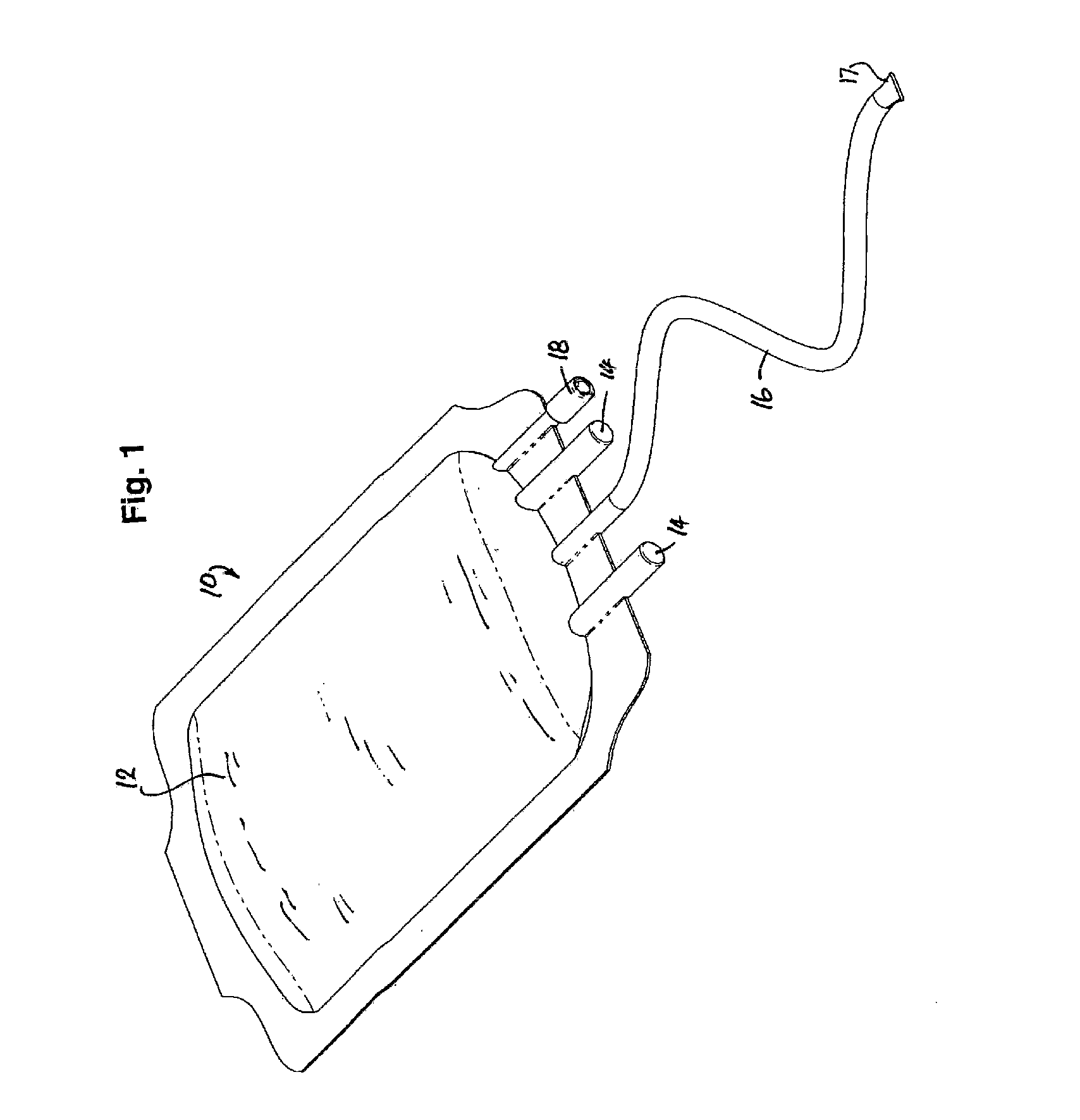
[0027]FIG. 1 shows a liquid container comprising a conventional sealed plastic pouch 10 containing a unit of platelets liquid, generally indicated at 12. Pouch 10 may have blanked-off tube connections 14 that may have been used during collection of the platelets but it will generally have at least one attached outlet or pouch tube 16 that is heat-sealed at its free end 17. Pouch 10 may also be provided with a split-septum needless port 18 through which a hollow blunt cannular can be inserted to extract samples of liquid 12. Samples of liquid may also be drawn from tube 16 by the use of a syringe and sharp medical needle. As already noted, both these methods of withdrawing samples involve contamination risk, both to the extracted sample and to the liquid in the pouch.

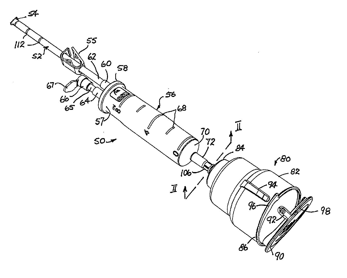
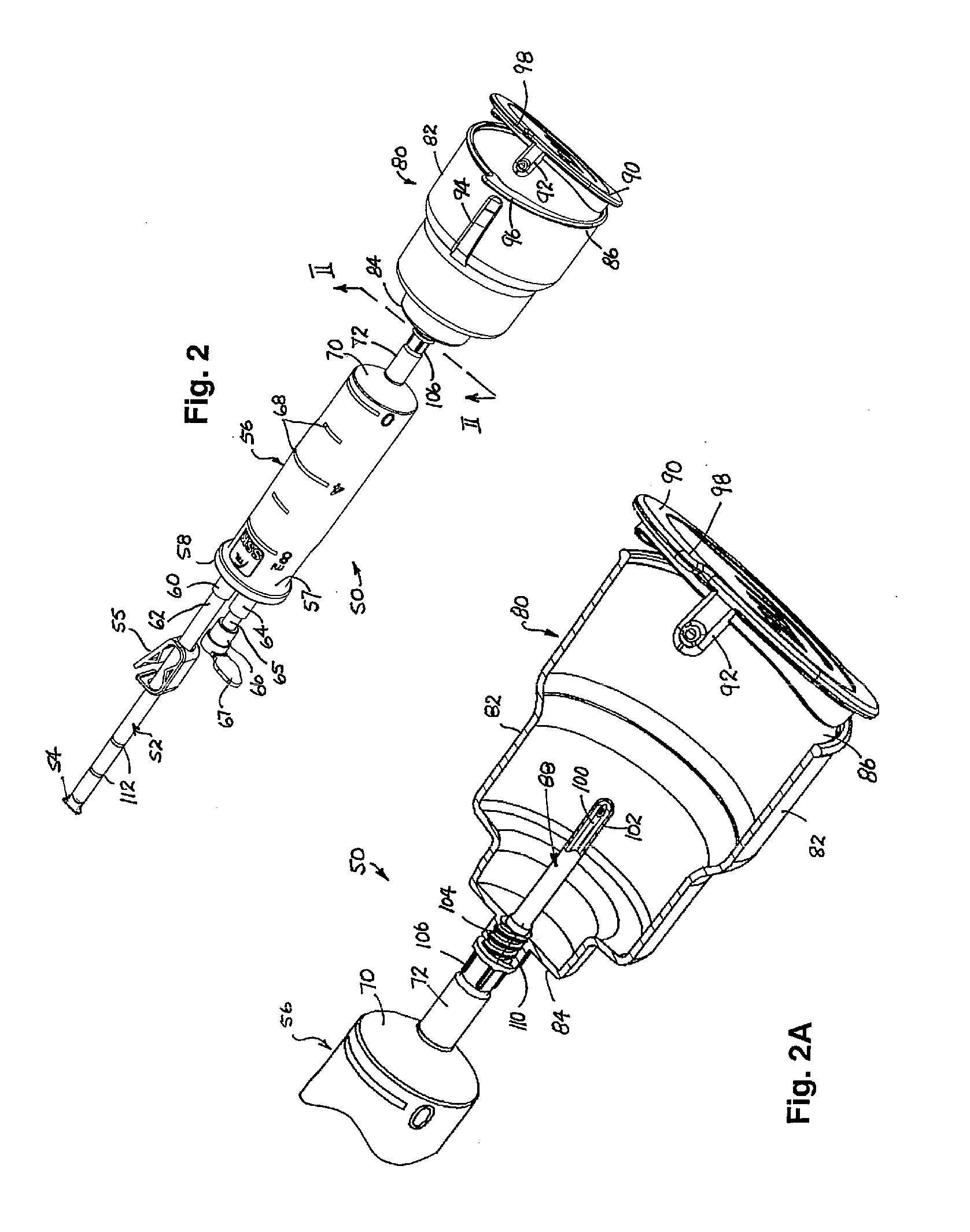
[0028]Turing now to FIGS. 2, 2A and 3, the apparatus 50 of the preferred embodiment will now be described. Apparatus 50 is preferably supplied as a sterile unit. It has a plastic inlet or sample tube 52 that is that is h...


PUM


Abstract

An apparatus and method that allow multiple samples of a liquid in a primary container (here called a ‘pouch’) to be taken with minimal danger of contaminating the liquid in the container during the sampling process are disclosed. In an embodiment, a closed sterile sight chamber is connected with the pouch in a sterile manner to allow fluid to flow into the chamber while at the same time allowing air within the chamber to be displaced through a bacterial filter to atmosphere. The connection between the sight chamber and the pouch is then terminated (severed or closed), isolating the pouch from the sampling apparatus. Only then are samples of liquid withdrawn from the sight chamber, while allowing air to flow into the chamber through the bacterial filter.

Description

CROSS-REFERENCE TO RELATED APPLICATIONS[0001]The current application is a Continuation in Part of co-pending U.S. patent application Ser. No. 10 / 990,820, filed Nov. 17, 2004, which claims priority from Australian provisional patent application serial number 2003906364, filed Nov. 19, 2003.FIELD OF THE INVENTION[0002]This invention relates to methods and apparatus for the sterile sampling of liquids in containers in ways that minimize the danger of contaminating the liquid in the container by the sampling process. It may be applied to the sampling of platelets and other blood products from collection pouches.[0003]For convenience and without meaning to exclude other forms of containers, the liquid containers to be sampled will herein be called pouches. As it will be normal for the pouch being sampled to be arranged above the sampling apparatus to take advantage of the hydrostatic head thus provided, it will be convenient to refer to parts of the apparatus as being above or below, or ...

Claims


Application Information

Patent Timeline
Patent Type & Authority Applications(United States)
IPC IPC(8): F03B11/02
CPCA61B5/1427A61B5/155A61J1/12G01N1/10A61M39/18A61M39/20A61M2039/0202A61M39/146A61B5/15003A61B5/150213A61B5/150366A61B5/1545A61B5/150992Y10T137/8593
Inventor KASHMIRAN, AVTAR SINGHNORRELL, STEPHANIE M.MOBBS, WILLIAM LEONARDWILSON, CRAIG DOUGLAS
Owner NOBLE HOUSE GROUP
Why Eureka
Try Eureka