Vacuum process apparatus

a technology of vacuum process and vacuum chamber, which is applied in the direction of lighting and heating apparatus, charge manipulation, furnaces, etc., can solve the problems of lack of flexibility, and achieve the effect of minimizing the cycle time of processing, minimizing the space possible, and high construction flexibility

Inactive Publication Date: 2008-04-01
OC OERLIKON BALZERS AG
View PDF20 Cites 1 Cited by
  • Summary
  • Abstract
  • Description
  • Claims
  • Application Information

AI Technical Summary

Benefits of technology

[0015]It is a further object to provide a vacuum process apparatus which gives a high degree of constructional freedom with respect to the arrangement of the said stations as concerns their orientation in space and especially the spatial arrangement of their respective openings. Thereby it shall be made possible to vastly increase the compactness of such process apparatuses, thereby optimizing assembly, disassembly, operation cycle time etc.
[0019]It has been recognized basically that, when providing a transporting device which is rotatable around the said axis and wherearound the openings of the said stations are arranged so that the normals on the areas defined by the respective borders of said openings are warped with respect to the said rotational axis, a highest grade of constructional flexibility is gained in order to design apparatuses more compact and / or to produce smallest possible spaces to be evacuated and / or to minimize cycle time of processing due to minimizing the conveyant distance between respective openings of the stations.
[0020]It is yet a further object to provide the said apparatus wherein said conveyor means are movable at least one of parallel to said axis and of radially to said axis. Thereby, departing from the rotational axis of the transport device, by appropriate selection of the movability of the said conveyor means, parallel and / or radial with respect to said axis, it becomes possible to reach openings of the said stations arranged with respect to the rotational axis in a great variability of different positions.
[0021]A further object of the present invention is to provide said apparatus wherein said conveyor means, once positioned adjacent one of said openings by rotating said transport device, are movable towards and from said opening in a direction given by the normal on the opening area defined by the said opening. Thereby an even simplified apparatus is realized in that it becomes possible to convey a workpiece disposed on the conveyor means considered straight ahead towards or into or through the opening of a station considered.
[0028]It is still a further object of the present invention to provide a vacuum process apparatus in which the stations communicate by the said openings with the inside of a chamber, said transport device residing within the said chamber. On one hand, by such a design the transport device is protected and further the danger of contamination of the atmosphere prevailing within the stations is decreased because, as mentioned, the openings of the stations communicate with the chamber.

Problems solved by technology

By providing such a vacuum process apparatus the disadvantages of the prior art apparatus as concerns lack of flexibility with respect to arranging more or less of the said stations at the apparatus are remedied and further the self-contained transport device with conveyor means and said driving means enables to drive said conveyor means without necessity of frictional seals at the process apparatus vacuum chamber wall, through which, according to prior art, such driving means did act on the conveyor means of the known transport device.

Method used


Image

  • Vacuum process apparatus
  • Vacuum process apparatus
  • Vacuum process apparatus

Examples


Embodiment Construction

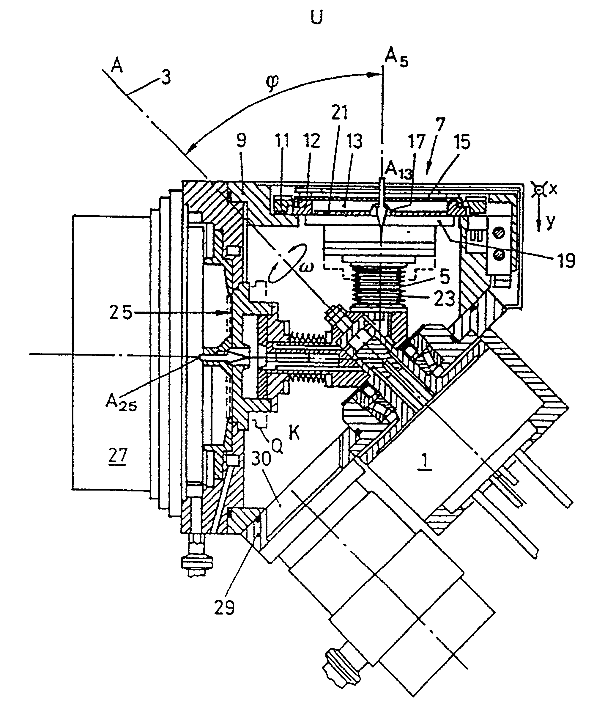
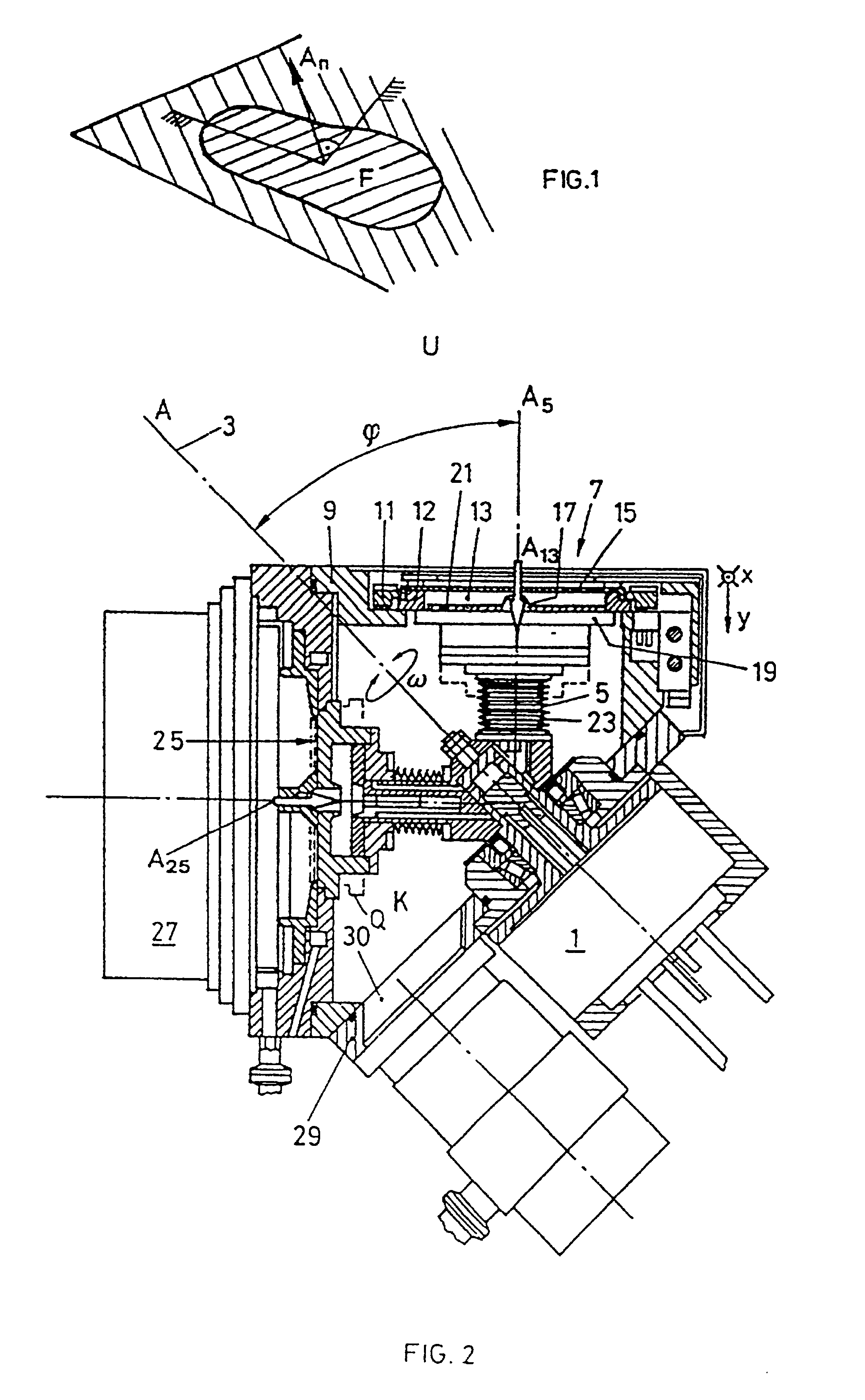
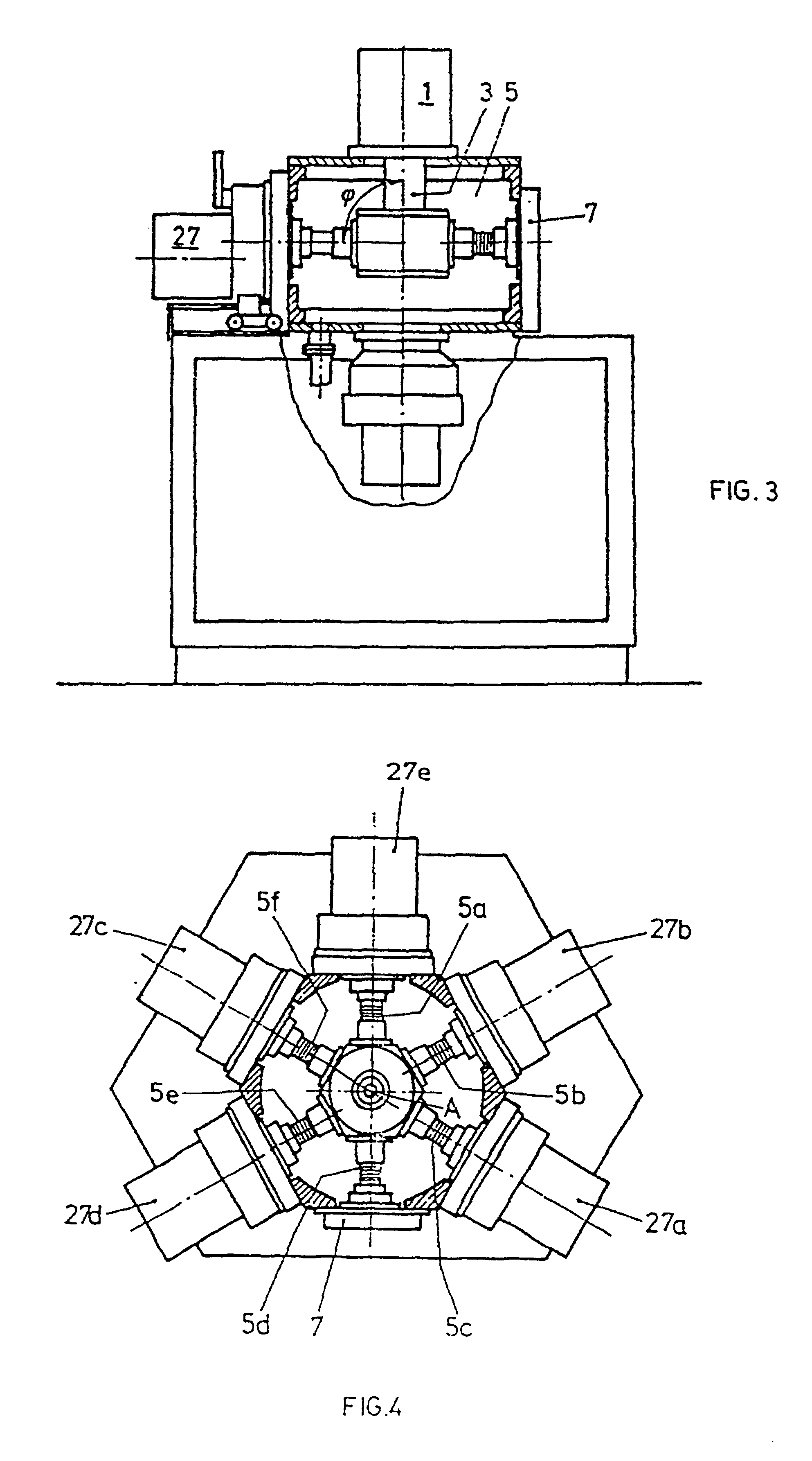
[0043]FIG. 2 is an illustration designed in section of an inventive vacuum process apparatus in a first configuration. It includes a drive motor 1 on the axis A as physical drive axis 3, to which at least one transport arm 5 is mounted. The axis A5 of the arm 5 extends at an angle, for instance of 45° relative to the rotation axis A. If the drive axis 3 is caused to rotate by means of the motor 1 such as indicated by ω, the transport arm(s) 5 sweeps over a conical trajectory surface having a cone angle φ of 45°. Two stations are illustrated in FIG. 2. A first station 7 is for instance and as illustrated designed as load lock. It includes a first frame 9 and a second frame 11 which can be moved upwards and downwards and which is flanged onto the first frame 9. Inside of the drivingly upwards and downwards movable frame 11 a sealing frame 12 is provided which determines the opening 13 of the station and thus its area, having a surface normal A13 of said area. The lock station 7 includ...


PUM

PropertyMeasurementUnit
cone opening angleaaaaaaaaaa
opening angleaaaaaaaaaa
cone angleaaaaaaaaaa

Abstract

The invention proceeds from a vacuum process apparatus for an article which is processed or treated, resp. at two stations, whereby each station has a charging and / or removing opening for the article. A transporting device is supported for rotation and includes a supporting portion which is successively moved onto the openings of the stations. The process plant is designed in such a manner that the surface normals determined by the surfaces of the openings and the space axis defined by the axis of rotation of the transport device do not run parallel and rather enclose together an angle of 90° or 45°. By such an arrangement it is possible to design extremely compact vacuum vapor deposition apparatuses having a plurality of individual stations, whereby additionally short transporting distances are obtainable and the volumes to be conditioned can be minimized.

Description

[0001]This application is a continuation of application Ser. No. 08 / 962,776, filed Nov. 3, 1997, which is a continuation of Reissue application Ser. No. 08 / 530,778, filed Sep. 19, 1995 abandoned, which is a reissue of application Ser. No. 888,111, filed May 26, 1992 (patented Sep. 21, 1993 as U.S. Pat. No. 5,245,736).BACKGROUND OF THE INVENTION[0002]1. Field of the Invention[0003]The present invention relates to a vacuum process apparatus of the kind, including at least two stations for treating or handling the workpiece, and a transport device with conveyor means thereon, each for transporting at least one workpiece from station to station.[0004]2. Description of the Prior Art[0005]The German specification DE-A-24 54 544 and “Patent Abstracts of Japan”, Nov. 28, 1989, vol. 13, no. 532, JP-A2 1-218 627, disclose as an example such a vacuum process apparatus which includes at least two stations, each comprising an opening for an article, the openings each determining an opening area ...

Claims


Application Information

Patent Timeline
Patent Type & Authority Patents(United States)
IPC IPC(8): B23B15/00B25B11/00B01J3/00B01J3/02B65G49/07C23C14/34C23C14/50C23C14/56C23C16/44G11B7/26G11B11/10G11B11/105H01L21/00H01L21/677
CPCC23C14/50C23C14/568H01L21/67745H01L21/67751Y10T29/49998Y10T29/5124Y10T29/5196C23C14/566C23C16/4585C23C16/54C23C16/4409B01J3/04
Inventor SCHERTLER, ROMAN
Owner OC OERLIKON BALZERS AG
Why Eureka
Try Eureka