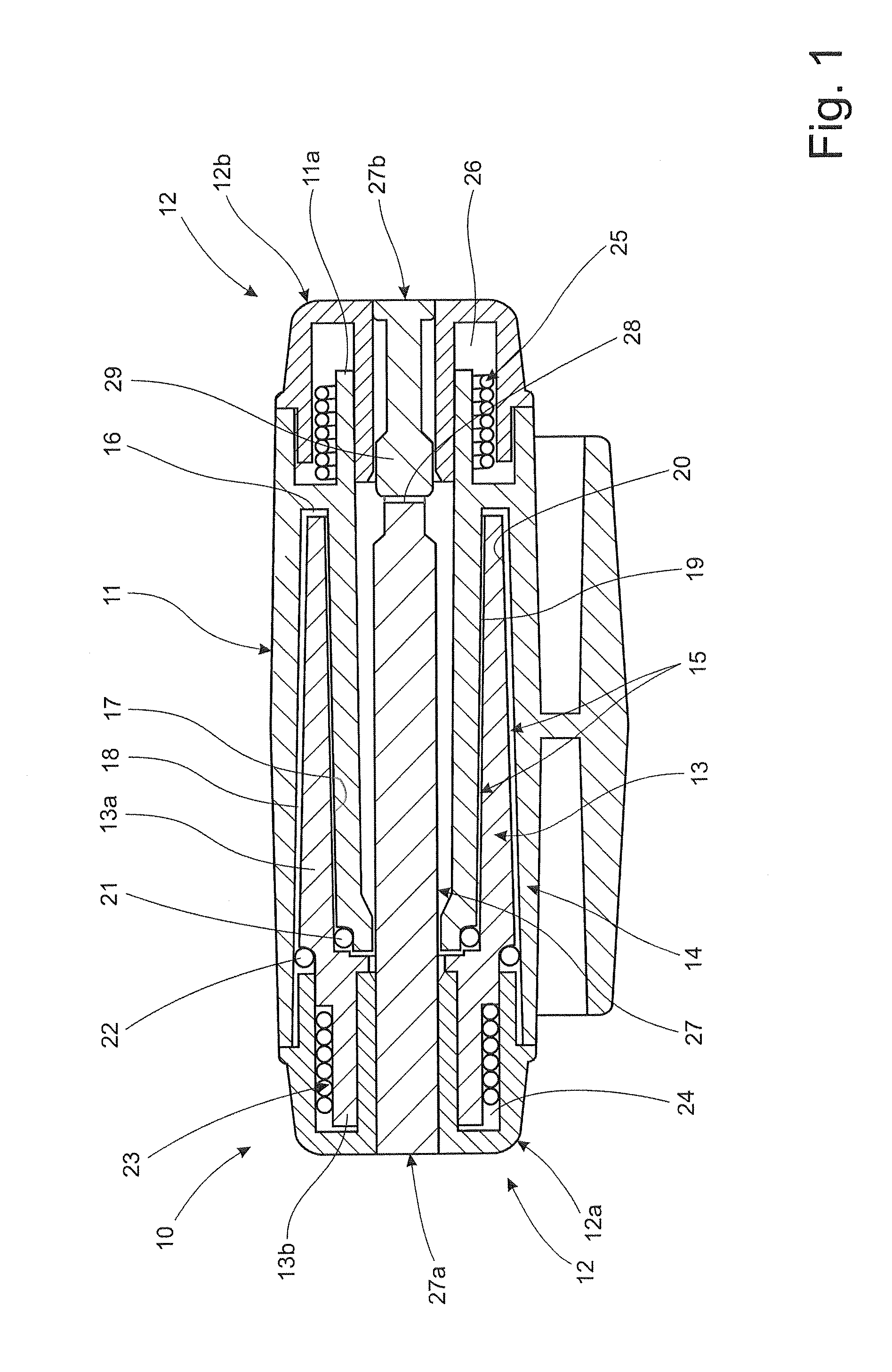
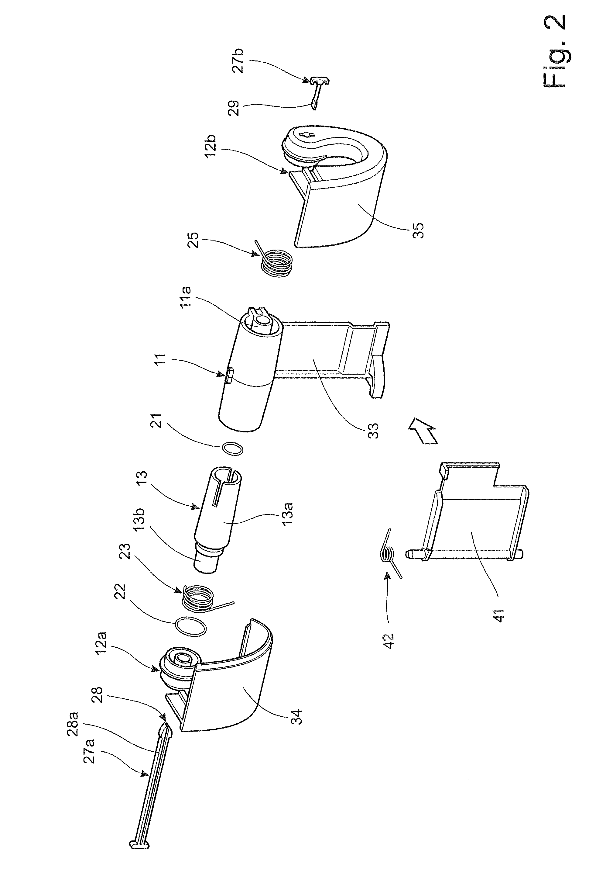
A second spring may be arranged between the first and second members. The second spring is connected to the respective first and second members so that rotation of the second member exerts a torque on said member towards the second position of the cover. Hence, when the cover is moved to the first position, the second member is rotated in the first direction relative to the fixed first member. The second spring may be, for instance, a
coil spring, which is gradually tensioned or pre-stressed as the cover is moved to the first position. When the cover is released, the torque exerted on the second member by the
coil spring will initiate the closing of the cover. As stated above, the movement towards the second position will be dampened, or resisted, by the
damper element provided between the first and the third members.
For example, the container may be a waste bin provided with a hinged cover comprising a hinge with such first and second springs. A user opening the cover by pivoting the cover in the first direction towards a first position, corresponding to the open position, is only required to overcome the action of the second spring as the
damper element is inactive during rotation in the said first direction. When released, the cover will begin to move towards a second position, corresponding to the initial closed position, by pivoting in the second direction under the action of the second spring. The first spring will actuate the damping element which ensures that the closing movement will be performed in a controlled manner, at a relatively
slow speed, by limiting the relative rate of rotation between the first and the third members.
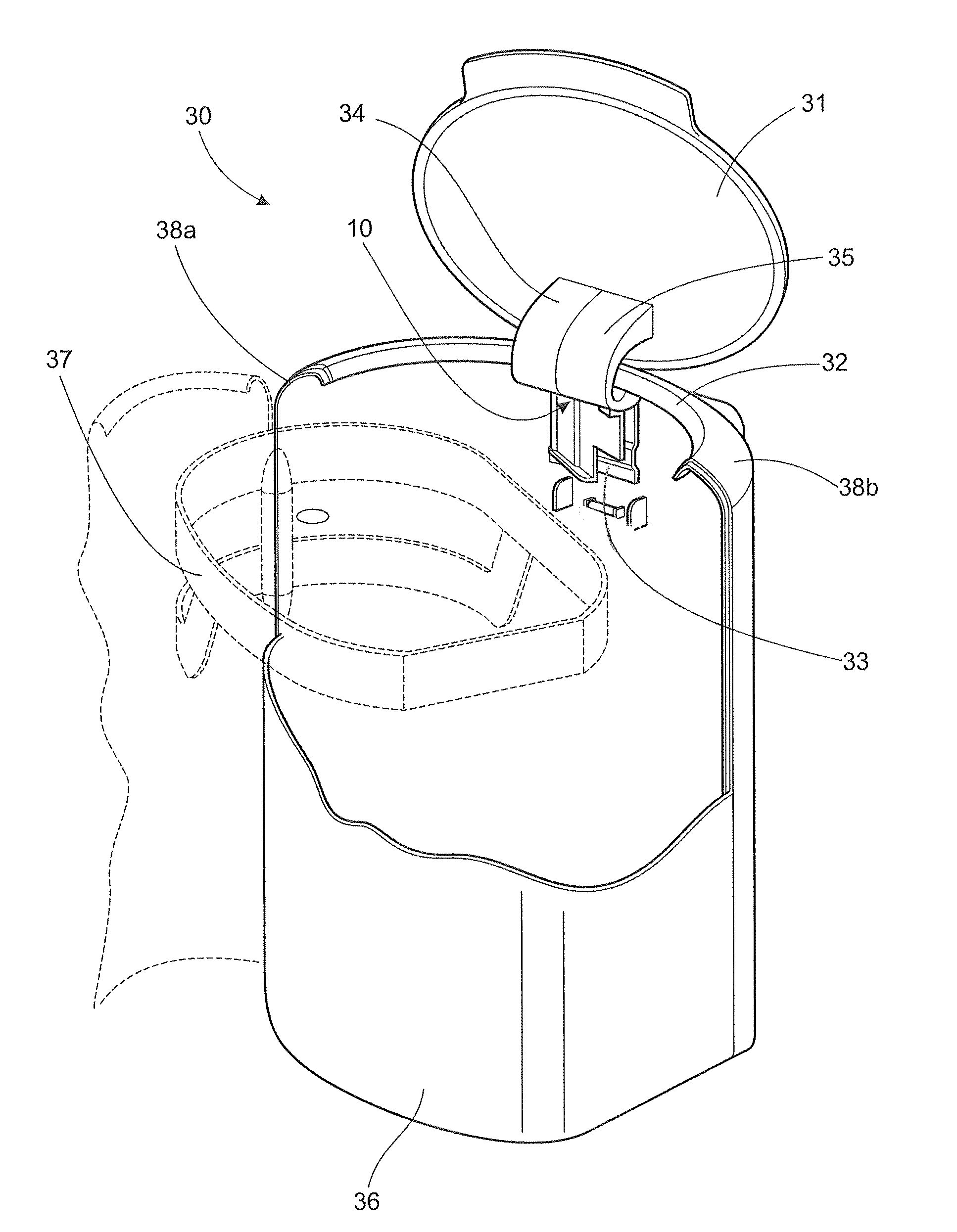
According to a further example, the container may be a dispenser provided with a cover hinged at the upper portion of the dispenser by a hinge comprising such first and second springs. A user opening the cover by pivoting the cover in the first direction towards a first position, corresponding to the open position, is only required to overcome the action of the second spring as the damper element is inactive during rotation in the said first direction. When released, the cover will begin to move towards a second position, corresponding to the initial closed position, by pivoting in the second direction under the action of the second spring. Depending on the degree of opening of the cover in the outwards and upwards direction, the second spring may be eliminated as the cover may return by gravity under its own weight. The damping element ensures that the closing movement will be performed in a controlled manner, at a relatively
slow speed, by limiting the relative rate of rotation between the first and the third members.
According to a further example, the container may be a dispenser provided with a cover hinged at the lower portion of the dispenser by a hinge comprising such first and second springs. A user wishing to open the cover is only required to release the cover, for instance by actuating a
locking mechanism. The cover will begin to move towards a second position, in this case corresponding to the open position, by pivoting the cover in the second direction under the action of the second spring. The first spring actuates the damping element which ensures that the opening movement will be performed in a controlled manner, at a relatively
slow speed, by limiting the relative rate of rotation between the first and the third members. After re-filling or servicing the dispenser, the user will close the cover by pivoting the cover in the first direction towards a first position, here corresponding to the initial closed position. During this movement the user is only required to overcome the action of the second spring as the damper element is inactive during rotation in the said first direction. The closing movement will pretension the first spring so that it is ready to initiate the opening movement of the cover upon a subsequent release of the
locking mechanism.
For a hinge located at a lower portion of the dispenser where the covers are being opened in an outwards and downwards direction, the first direction, as defined above, will correspond to the closing of the cover and the second direction will correspond to the opening of the cover. For dispensers of this type, the hinge will prevent the cover from dropping uncontrollably outwards and downwards. Also, as such covers are maintained in the opened position by gravity, the blocking mechanism described above may be dispensed with.

