Self-healing power amplifier: methods and apparatus

a power amplifier and self-healing technology, applied in the field of power amplifiers, can solve the problems the need to “trim” or adjust the circuit, and the inability to achieve the effect of reducing the performance of the power amplifier, and achieving the effect of optimizing the power amplifier performance metri

Active Publication Date: 2011-06-16
CALIFORNIA INST OF TECH
View PDF4 Cites 33 Cited by
  • Summary
  • Abstract
  • Description
  • Claims
  • Application Information

AI Technical Summary

Benefits of technology

[0006]According to one aspect, the invention features an integrated power amplifier which includes a divider having a divider input terminal and two or more divider output terminals. The divider input terminal is electrically coupled to a power amplifier input terminal. A combiner having two or more combiner input terminals and a combiner output terminal are electrically coupled to a power amplifier output terminal. The integrated power amplifier also includes two or more amplifiers, each amplifier having an amplifier input terminal and an amplifier output terminal. Each of the amplifier input terminals is electrically coupled to a divider output terminal and each of the amplifier output terminals is electrically coupled to a combiner input terminal. At least one power sensor is configured to provide a power amplifier performance metric. At least one terminal is configured to receive an electrical voltage to power the integrated power amplifier. The divider and the combiner include a plurality of actuators. Each actuator of the actuators has at least one actuator control terminal which is configured to provide an actuator setting. The actuators are configured via the actuator control terminals to optimize the power amplifier performance metric.

Problems solved by technology

These variations can result in divergent operation of what should be identical devices.
One problem that this can create is the necessity to “trim” or adjust circuits to achieve acceptable operation.
In the worst of cases, the variation can result in the need to reject or to discard chips that fall outside a desired operational envelope.
Especially problematic are designs which include a RF power amplifier (PA), such as a high frequency (e.g. mm-wave) PA.

Method used


Image

  • Self-healing power amplifier: methods and apparatus
  • Self-healing power amplifier: methods and apparatus
  • Self-healing power amplifier: methods and apparatus

Examples


Embodiment Construction

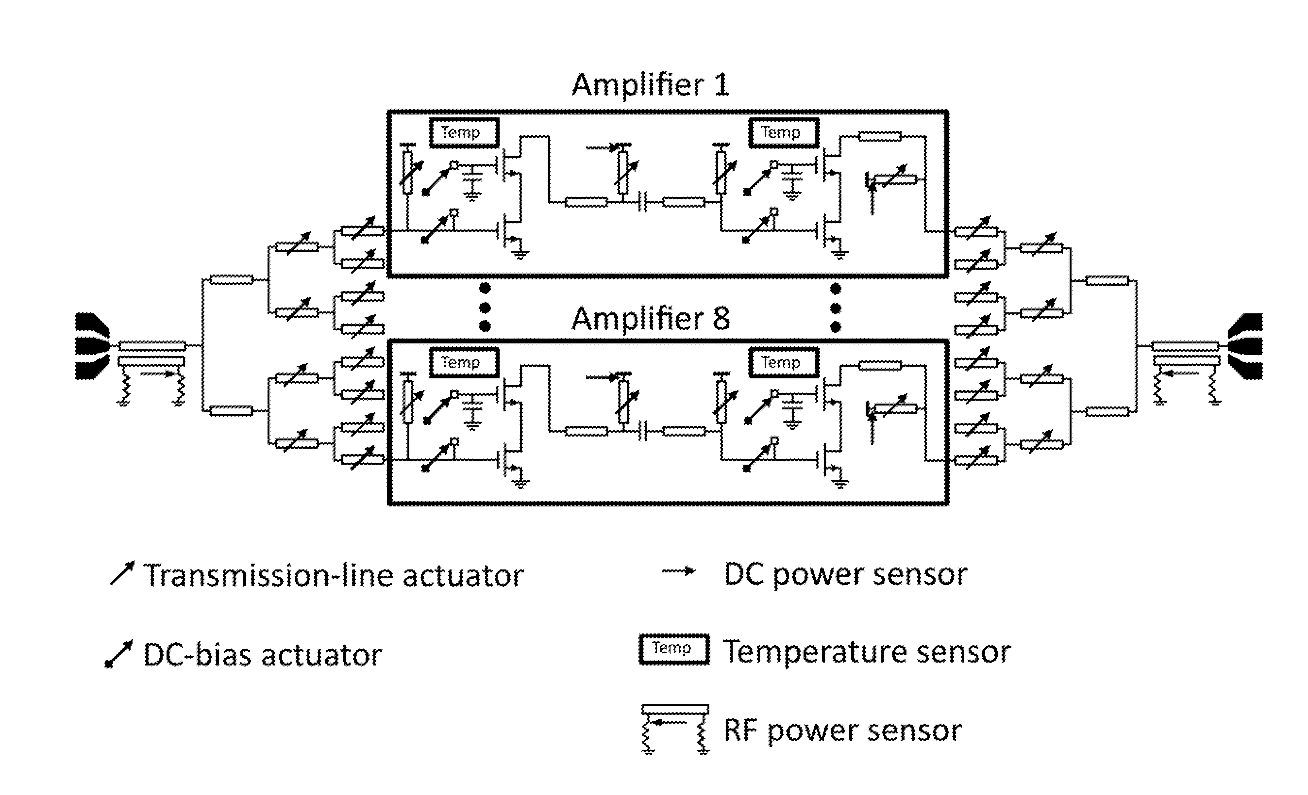
[0120]We describe hereinbelow robust RF / analog circuitry for use in highly stochastic power amplifier design spaces (e.g., process variations and operational environmental factors) which includes built-in circuitry such that the system can detect imperfections and correct for its intrinsic flaws autonomously. In such a power amplifier system, “sensors” and “actuators” are added throughout the design. A loop can be closed and sensor outputs can be used to determine, for example, by use of digital processing, values for actuator settings which are expected to improve the performance of the RF / analog circuitry, such as a power amplifier. Such autonomous corrections (also referred to as “self healing”) can be performed automatically during operation of the RF / analog circuitry.

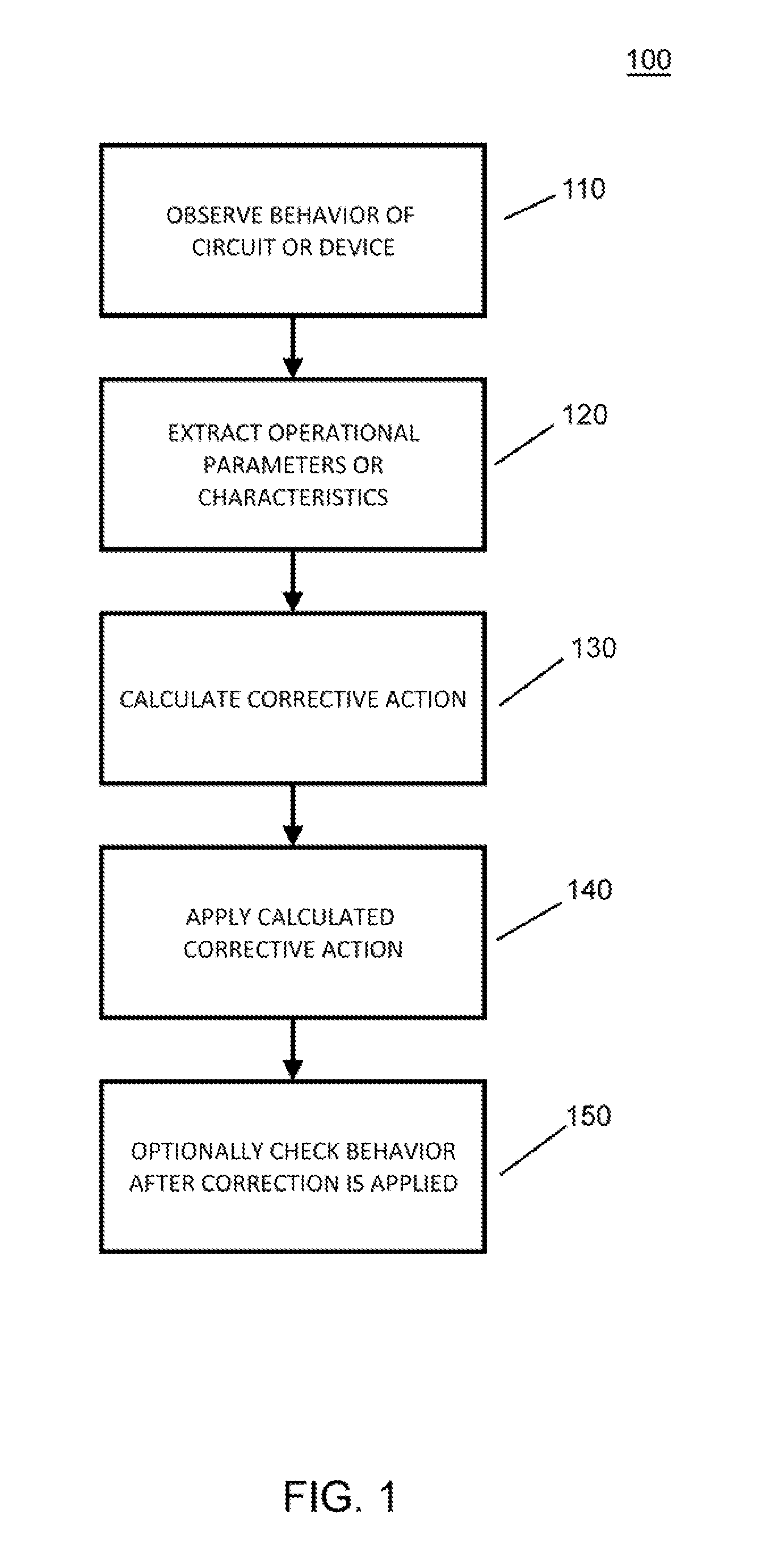
[0121]FIG. 1 shows an exemplary schematic flow chart 100 of the overall system and process for a self-healing circuit or device. As illustrated in FIG. 1, at step 110, the behavior of a circuit or a device in respo...


PUM


Abstract

An integrated power amplifier includes a divider and a combiner. The integrated power amplifier also includes two or more amplifiers. Each of the amplifier input terminals is electrically coupled to a divider output terminal and each of the amplifier output terminals is electrically coupled to a combiner input terminal. At least one power sensor is configured to provide a power amplifier performance metric. The divider and the combiner include a plurality of actuators. Each actuator has at least one actuator control terminal which is configured to provide an actuator setting. The actuators are configured via the actuator control terminals to optimize the power amplifier performance metric. Methods to simulate the operation of a self-healing power amplifier and a process for the operation of a self-healing circuit are also described.

Description

CROSS-REFERENCE TO RELATED APPLICATIONS[0001]This application claims priority to and the benefit of co-pending U.S. provisional patent application Ser. No. 61 / 285,088, Self-healing Power Amplifier: Methods and Apparatus, filed Dec., 9, 2009. This application is related to co-pending U.S. patent application Ser. No. 12 / 806,906, filed Aug. 24, 2010, entitled ELECTRONIC SELF-HEALING METHODS FOR RADIO-FREQUENCY RECEIVERS, and co-pending U.S. patent application Ser. No. 12 / 877,743, filed Sep. 8, 2010, entitled SELF-HEALING TECHNIQUE FOR HIGH FREQUENCY CIRCUITS. All of the enumerated applications above are incorporated herein by reference in their entirety for all purposes.STATEMENT REGARDING FEDERALLY FUNDED RESEARCH OR DEVELOPMENT[0002]The U.S. Government has certain rights in this invention pursuant to a Grant awarded by the Air Force Office of Scientific Research under Contract number FA8650-09-C-7924.FIELD OF THE INVENTION[0003]The invention relates to power amplifiers in general and...

Claims


Application Information

Patent Timeline
Patent Type & Authority Applications(United States)
IPC IPC(8): H03F3/68G06F17/50
CPCH03F1/0266H03F2203/21142H03F1/223H03F1/301H03F1/565H03F3/005H03F3/195H03F3/211H03F3/24H03F3/601H03F3/604H03F2200/105H03F2200/15H03F2200/18H03F2200/222H03F2200/318H03F2200/387H03F2200/411H03F2200/451H03F2203/21106H03F1/0272
Inventor SENGUPTA, KAUSHIKBOWERS, STEVENBABAKHANI, AYDINCHANG, ARTHUR H.HAJIMIRI, SEYED ALI
Owner CALIFORNIA INST OF TECH
Why Eureka
Try Eureka