System and method for operating rotisserie oven

a rotisserie oven and rotisserie technology, applied in the field of cooking, can solve the problems of burden on users and disabled rotisserie driving assembly

Active Publication Date: 2011-06-16
WHIRLPOOL CORP
View PDF21 Cites 24 Cited by
  • Summary
  • Abstract
  • Description
  • Claims
  • Application Information

AI Technical Summary

Benefits of technology

[0004]The present invention is directed to an oven for performing a rotisserie cooking operation and a method of performing a rotisserie operation. In accordance with a preferred embodiment of the invention, the oven includes an oven cavity having a door movable between open and closed positions in order to selectively provide access to the oven cavity, at least one heating element exposed to heat the oven cavity and a rotisserie arm adapted to support a food product positioned within the oven cavity. A motor is operatively coupled to the rotisserie arm for driving the rotisserie arm and rotating the food product on the arm. The oven also includes a control interface having a rotisserie cooking mode input and a control system for controlling the rotisserie motor and the heating element. Most importantly, the control system enables the motor to further rotate the rotisserie arm even when the door is in the open position. In the most preferred form of the invention, the control system causes the rotisserie motor to cycle on and off to allow for an intermittent 360 degree rotation of the food product supported on the rotisserie arm while the oven door is in the open position.

Problems solved by technology

When the oven door is opened, the rotisserie driving assembly is disabled.
Obviously, this is burdensome to the user and would require accuracy to open the door at precisely the correct time when the desired part of the food product to be basted is exposed.

Method used


Image

  • System and method for operating rotisserie oven
  • System and method for operating rotisserie oven
  • System and method for operating rotisserie oven

Examples


Embodiment Construction

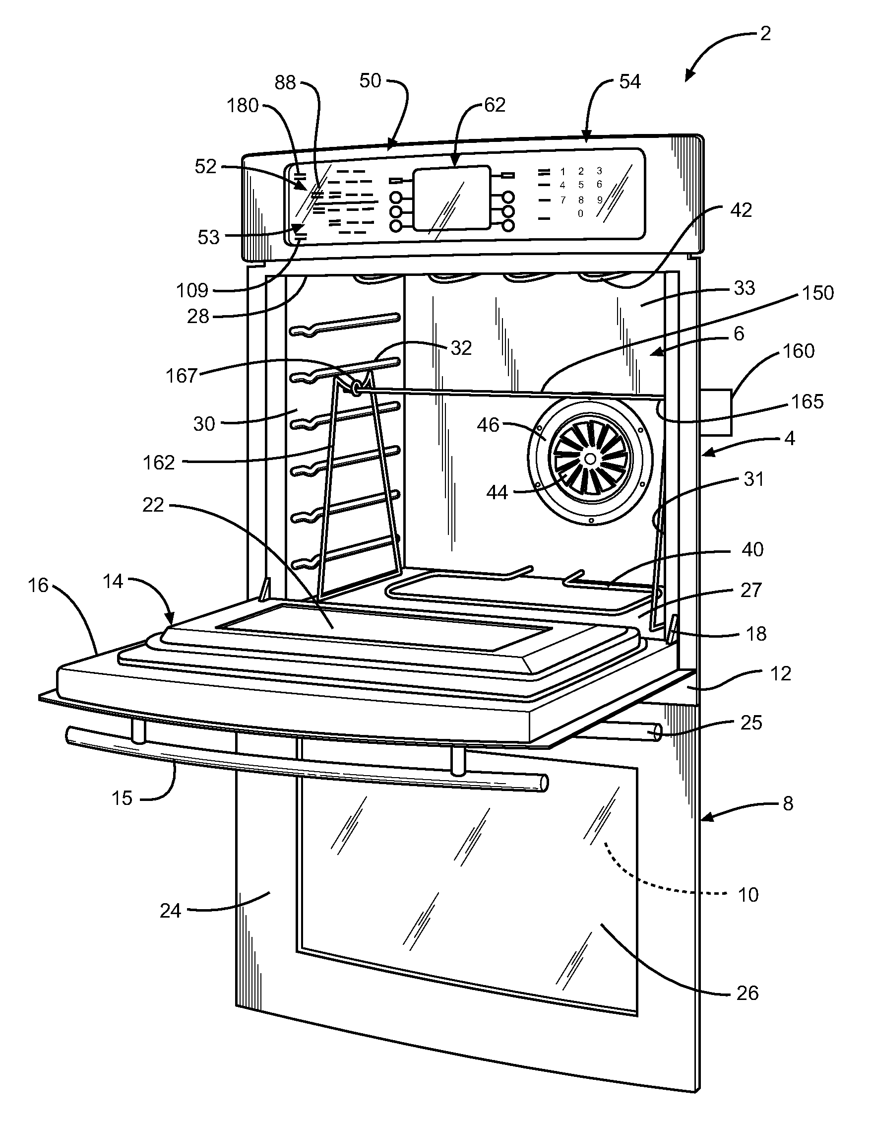
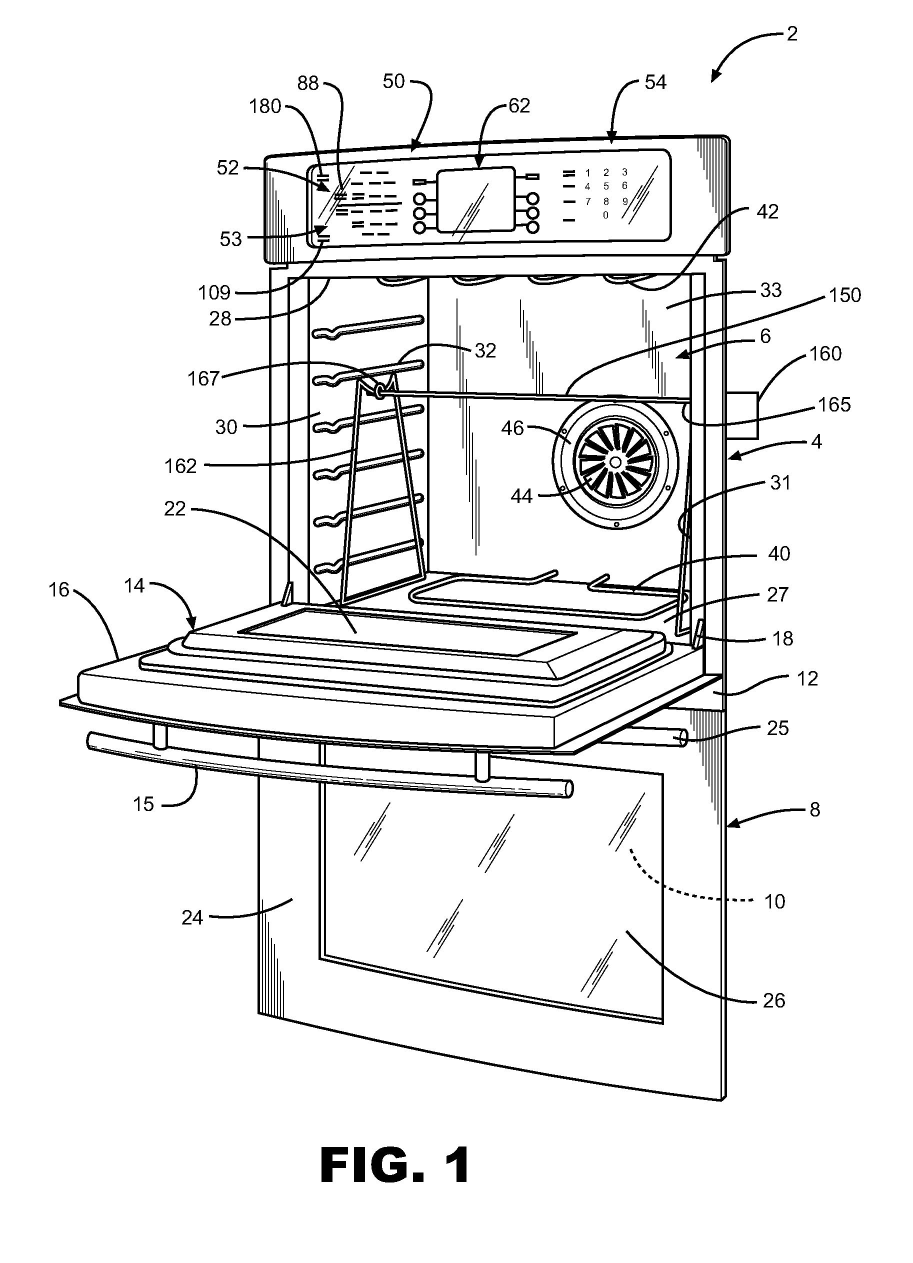
[0008]With initial reference to FIG. 1, a cooking appliance constructed in accordance with the present invention is generally indicated at 2. Cooking appliance 2, as depicted, constitutes a double wall oven. However, it should be understood that the present invention not limited to this model type and can be incorporated into various types of oven configurations, e.g., cabinet mounted ovens, as well as both slide-in and free standing ranges. In any event, in the embodiment shown, cooking appliance 2 constitutes a dual oven wall unit including an upper oven 4 having upper oven cavity 6 and a lower oven 8 having a lower oven cavity 10. Cooking appliance 2 includes an outer frame 12 for supporting both upper and lower oven cavities 6 and 10.

[0009]In a manner known in the art, a door assembly 14 is provided to selectively provide access to upper oven cavity 6. As shown, door assembly 14 includes a handle 15 at an upper portion 16 thereof. Door assembly 14 is adapted to pivot at a lower ...


PUM


Abstract

An oven for performing a rotisserie cooking operation includes an oven cavity having a door for selectively accessing the oven cavity, at least one heating element for heating the oven cavity and a rotisserie arm adapted to support a food product within the oven cavity. A motor is operatively coupled to the rotisserie arm for rotating the rotisserie arm and a food product. The oven also includes a control interface having a rotisserie cooking mode input and a control system for controlling the rotisserie motor and the heating element. In addition to other functions, the control system automatically causes the rotisserie motor to cycle on and off to allow for intermittent rotation of the food product supported on the rotisserie arm when the oven door is opened.

Description

FIELD OF THE INVENTION[0001]The present invention pertains to the art of cooking and, more particularly, a system and method of operating a rotisserie oven.DESCRIPTION OF THE RELATED ART[0002]In general, placing a rotisserie assembly in a domestic oven is known in the art of cooking appliances. In typical arrangements, a rotisserie arm is positioned in an oven cavity for supporting food to be cooked. The rotisserie arm is typically driven by a motor which causes the rotisserie arm and food to rotate at a constant speed. In this known arrangement, the motor is switched off when the oven door is opened to stop the rotation of the rotisserie arm in order to baste or brown the food supported on the rotisserie arm. For example, U.S. Pat. No. 5,639,497, which discloses a cooking control system for rotisserie ovens, includes an assembly for driving a food supporting spit. When the oven door is opened, the rotisserie driving assembly is disabled. Similarly, each of U.S. Pat. Nos. 5,361,686 ...

Claims


Application Information

Patent Timeline
Patent Type & Authority Applications(United States)
IPC IPC(8): A47J27/62A47J37/04A23L1/01A23L5/10
CPCA47J37/041A23L5/10F24C15/164A47J37/04A47J37/049
Inventor JOHNCOCK, JAMES C.KESHEH, FOAD M.SWAYNE, STEVEN M.
Owner WHIRLPOOL CORP
Why Eureka
Try Eureka