Guidewire

Inactive Publication Date: 2011-06-16
ASAHI INTECC CO LTD
View PDF14 Cites 4 Cited by
  • Summary
  • Abstract
  • Description
  • Claims
  • Application Information

AI Technical Summary

Benefits of technology

[0008]The present invention was made in view of the foregoing circumstances. An object of the present invention is to provide a guidewire effectively usable for the retrograde approach.

Problems solved by technology

This approach is not an operation for directly approaching a stenosis as a target treatment area.

Method used


Image

  • Guidewire
  • Guidewire
  • Guidewire

Examples


first embodiment

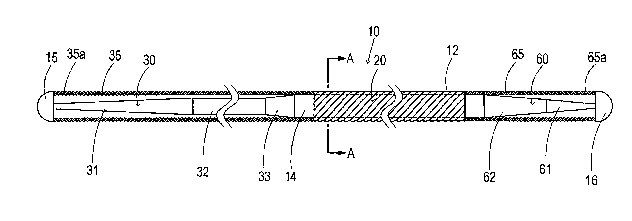
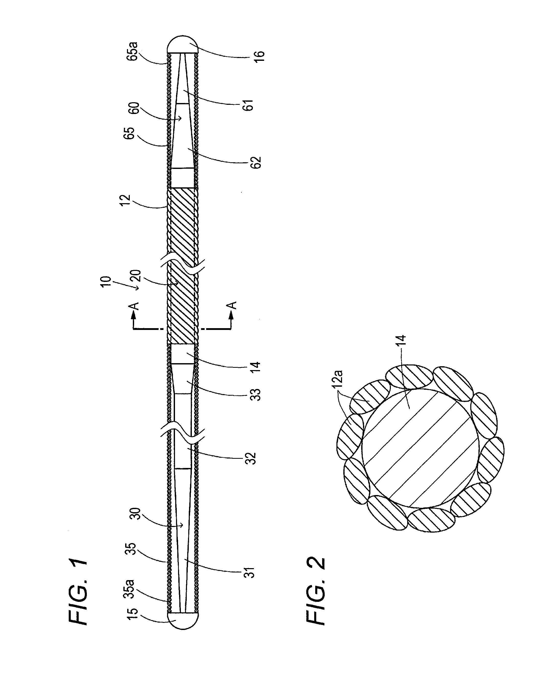
[0104]In the first embodiment described above, the stiffness of the body portion 20 is adjusted through use of the stranded coil 12 constituted by the core wire 14 and the plurality of strands. In this case, forming a desired outer diameter from the stranded coil 12 and using the core wire 14 that fits therewith enables subtle adjustment of the outer diameter and the stiffness of the guidewire 10. Further, the stranded coil 12 generally has a characteristic of having high torque transmissibility. For this reason, using the stranded coil 12 enables achievement of a flexible guidewire with high torque transmissibility.

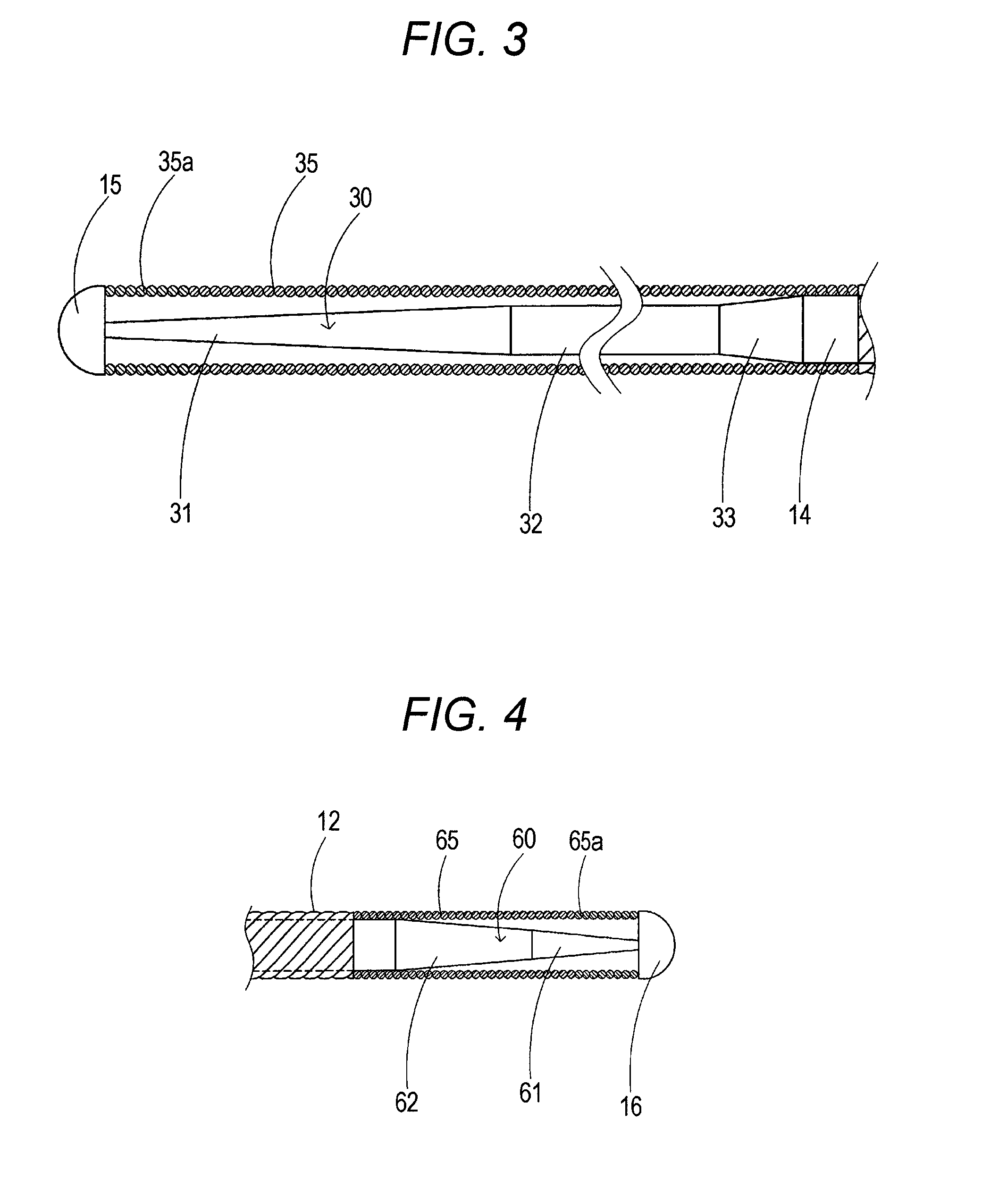
[0105]Moreover, surrounding the first tip portion 30 and the second tip portion 60 by the first coil 35 and the second coil 65 with substantially the same diameter as the stranded coil 12 enables achievement of such a shape that the guidewire 10 has substantially the same outer diameter as a whole. As the coils have substantially the same diameter, there is an advantage ...

third embodiment

[0108]Further, as a guidewire 610 of a third embodiment illustrated in FIG. 15, the guidewire may have a configuration where the core wire is surrounded by the same stranded coil in the first tip portion, the second tip portion, and the body portion. A first tip portion 630 of the guidewire 610 illustrated in FIG. 15 is surrounded by a stranded coil 612 constituted by a plurality of strands, as is a body portion 620. As for stiffness of the first tip portion 630, the stiffness may be changed only by decreasing the diameter of a core wire 614. However, in the case of the present embodiment, in addition to decreasing the diameter of the core wire 614 in a tapering manner, sequentially decreasing the number of strands constituting the stranded coil 612 as illustrated by 630a, 630b, and 630c increases the flexibility of the stranded coil 612 toward the tip. Thereby, the stiffness of the first tip portion 630 is adjusted.

[0109]Similarly, the stiffness of the first tip portion 630 may als...


PUM


Abstract

Provided is a guidewire effectively usable for a retrograde approach. A guidewire has a body portion, and a first tip portion and a second tip portion provided at ends of the body portion. Flexural stiffnesses of the first tip portion and the second tip portion increase in a continuous or stepwise manner from the respective tips of the first and second tip portions toward the body portion. The flexural stiffness of the first tip portion is not smaller in value than the flexural stiffness of the second tip portion in first distance ranges from the respective tips of the first and second tip portions toward the body portion. The flexural stiffness of the first tip portion is smaller in value than the flexural stiffness of the second tip portion in second distance ranges beyond the respective first distance ranges of the first and second tip portions toward the body portion.

Description

CROSS REFERENCE TO RELATED APPLICATIONS [0001]This application is based on Japanese Patent Application No. 2009-280881 filed with the Japan Patent Office on Dec. 10, 2009, the entire content of which is hereby incorporated by reference.TECHNICAL FIELD [0002]The present invention relates to a medical guidewire.BACKGROUND ART [0003]There have hitherto been proposed a variety of medical guidewires for guiding, e.g., a catheter which is used by being inserted into tubular organs such as blood vessels, digestive tracts, and ureters, and intracorporeal tissues (e.g., see JP 2003-052831A and U.S. Pat. No. 5,363,847).[0004]Further, there has recently been proposed an operation called a retrograde approach as a cardiac catheterization treatment method performed with use of a guidewire (e.g., see US 2007 / 0208368 A1). This approach is not an operation for directly approaching a stenosis as a target treatment area. More specifically, this approach is an operation for approaching the target sten...

Claims


Application Information

Patent Timeline
Patent Type & Authority Applications(United States)
IPC IPC(8): A61M25/09
CPCA61M25/09A61M2025/0915A61M2025/09083
Inventor SHIMOGAMI, MANABUKITAGAWA, MASANORI
Owner ASAHI INTECC CO LTD
Why Eureka
Try Eureka