Device and method for controlling internal combustion engine

a technology of internal combustion engine and control device, which is applied in the direction of electric control, machines/engines, mechanical equipment, etc., can solve the problems of incomplete oxidation reaction, difficult to completely oxidize pm discharged from the engine, and worse fuel consumption, and achieve excellent effect and effectively use ozone

Inactive Publication Date: 2012-06-05
TOYOTA JIDOSHA KK
View PDF18 Cites 5 Cited by
  • Summary
  • Abstract
  • Description
  • Claims
  • Application Information

AI Technical Summary

Benefits of technology

[0007]An object of the present invention is to provide a device and a method for controlling an internal combustion engine capable of effectively using ozone when PM is oxidized and removed.
[0010]According to this aspect, since the fuel injection of the internal combustion engine is interrupted during the execution of the ozone supply, it is possible to prevent the ozone-consuming components such as NOx or HC from being contained in exhaust gas (substantially air), whereby the supplied ozone is effectively usable for the oxidation of PM in the particulate matter trapping device.
[0012]When the fuel injection is interrupted, a relatively large amount of air flows into the particulate matter trapping device, and PM deposited in the particulate matter trapping device instantly burns by the influence of this air, whereby the temperature of the particulate matter trapping device abnormally rises to result in the inconvenience such as melting or crack thereof. According to this preferable aspect, since the interruption of fuel injection is executed when said forecasting means forecasts that the temperature of the particulate matter trapping device does not abnormally rises, it is possible to assuredly avoid the inconvenience such as the welding or crack of the particulate matter trapping device.
[0014]Ozone has a proper temperature window for the oxidation of PM, and ozone is thermally decomposed and disappears at a temperature higher than the temperature window. According to this preferable aspect, the supply of ozone is not executed until the temperature detected by the temperature detecting means becomes lower than the first predetermined value after the fuel injection has been interrupted by the fuel injection interrupting means, and ozone is supplied after the detected temperature becomes lower than the first predetermined value. Accordingly, it is possible to avoid the useless consumption of ozone until the detected temperature is lower than the first predetermined value, and after the detected temperature is lower than the first predetermined value, it is possible to use ozone for oxidizing PM while avoiding the disappearance of ozone, resulting in the effective application of ozone.
[0023]According to the present invention, an excellent effect is obtainable for effectively using ozone when PM is oxidized and removed by using ozone.

Problems solved by technology

There is a problem in the proposals wherein the fuel is forcibly supplied by the injection in that the fuel consumption becomes worse.
While, the proposal described in Japanese Patent Laid-Open No. 2002-537162 has a problem in that it is difficult to completely oxidizing PM discharged from the engine and removing the same since the oxidation speed of PM by NO2 is insufficient.
H9-125931, there is a problem in that, since the catalyst and PM are a solid substance, the both are not sufficiently in contact with each other and result in the incomplete oxidation reaction.
However, there is a risk in that ozone having a high oxidation power may be consumed by the preferential reaction with NOx or HC in the exhaust gas prior to being introduced into the particulate filter, resulting in a problem that an amount of ozone usable for the oxidation and removal of PM becomes less to lower the cleaning efficiency and the oxidation speed of PM.

Method used


Image

  • Device and method for controlling internal combustion engine
  • Device and method for controlling internal combustion engine
  • Device and method for controlling internal combustion engine

Examples


Embodiment Construction

[0028]Embodiments of the present invention will be described below with reference to the attached drawings.

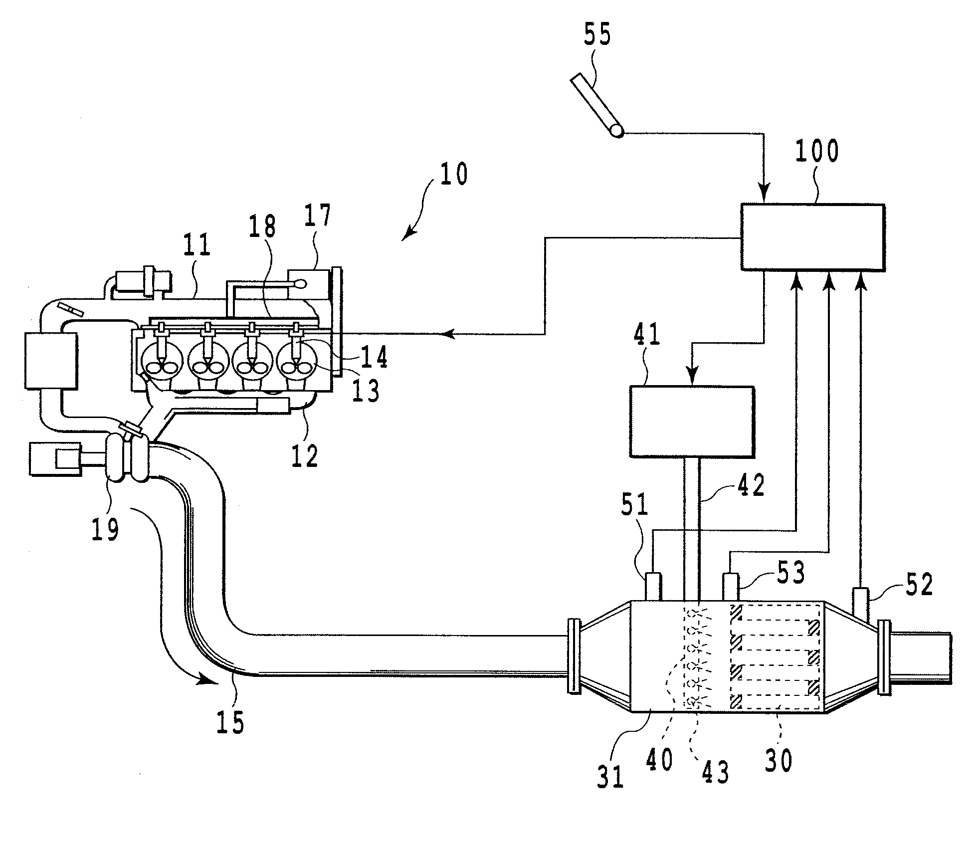
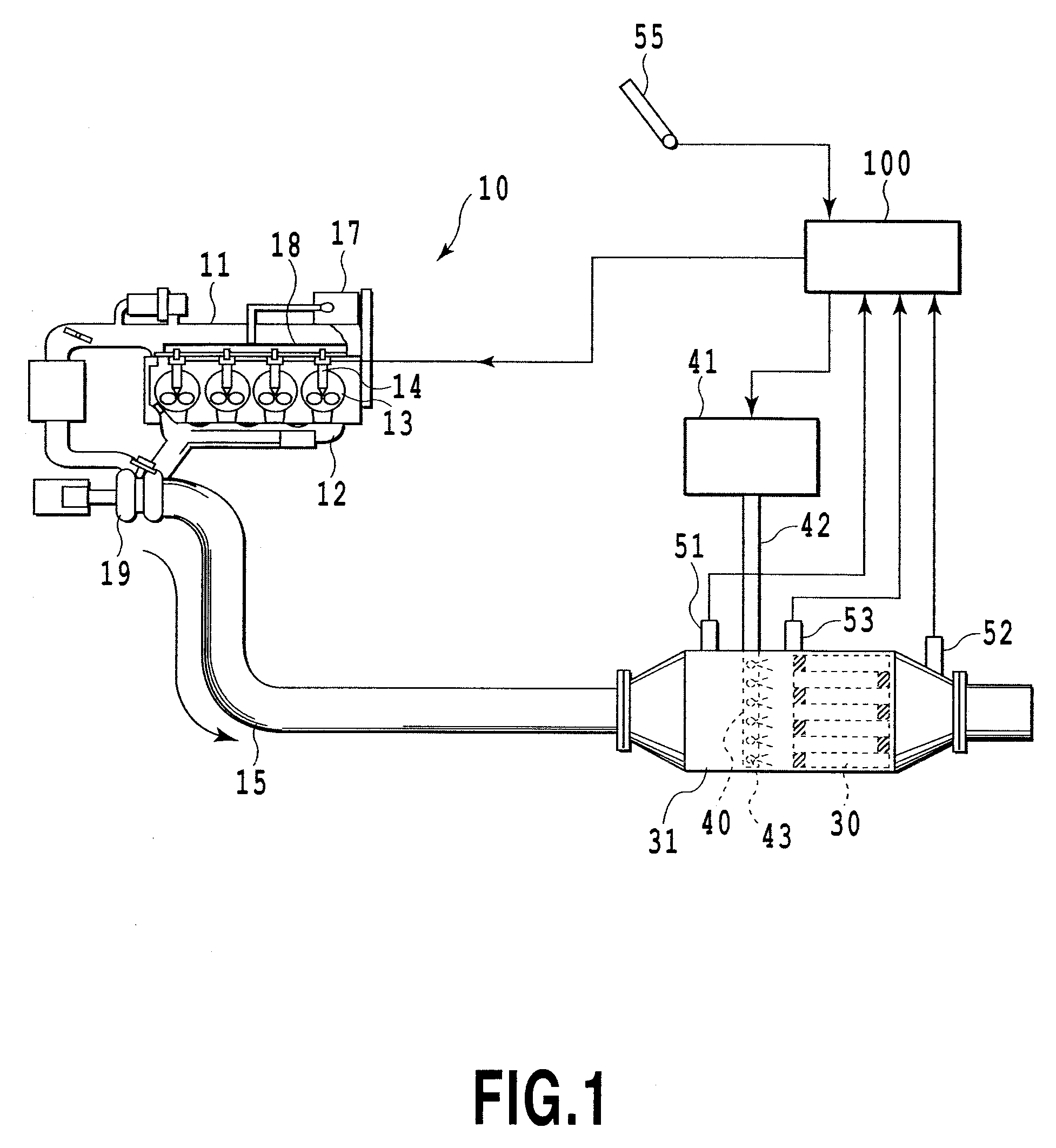
[0029]FIG. 1 is a system diagram diagrammatically illustrating a device for controlling an internal combustion engine according to an embodiment of the present invention. In the drawing, reference numeral 10 denotes an internal combustion engine of a compressive ignition type; that is, a diesel engine in a case of this embodiment. Reference numeral 11 denotes an air-intake manifold communicated with an air-intake port, 12 denotes an exhaust manifold communicated with an exhaust port, and 13 denotes a combustion chamber. In this embodiment, fuel supplied from a fuel tank not shown to a high-pressure pump 17 is pumped to a common rail 18 and accumulated there at a high pressure, which fuel in the common rail 16 is then injected into the combustion chamber 13 directly from a fuel injection valve 14. Exhaust gas from the diesel engine 10 enters the exhaust manifold 12 and then a tu...


PUM


Abstract

A device for controlling an internal combustion engine comprises a device for trapping particulate matter (PM) in exhaust gas in an exhaust passage, means for supplying ozone to the particulate matter trapping device from the upstream thereof to oxidize and remove PM deposited in the device, and means for interrupting the fuel injection of the internal combustion engine upon the execution of ozone supply by the ozone supply means. It is possible to prevent components consuming ozone, such as NOx, from being contained in the exhaust gas of the internal combustion engine, whereby ozone is effectively usable.

Description

CROSS-REFERENCE TO RELATED APPLICATIONS[0001]This application is a national phase application of International Application No. PCT / JP2007 / 063769, filed Jul. 4, 2007, and claims the priority of Japanese Application No. 2006-185963, filed Jul. 5, 2006, the contents of both of which are incorporated herein by reference.FIELD OF TECHNOLOGY[0002]The present invention relates to a device and a method for controlling an internal combustion engine, particularly to those in which the engine comprises an exhaust gas cleaning apparatus for cleaning particulate matter in exhaust gas discharged from a diesel engine by trapping and oxidizing the particulate matter.BACKGROUND ART[0003]It has been known in general that the exhaust gas discharged from the diesel engine contains particulate matter (hereinafter referred to PM) mainly composed of carbon, causing the atmospheric contamination. Accordingly, various devices and methods have been proposed, for trapping the particulate matter and removing i...

Claims


Application Information

Patent Timeline
Patent Type & Authority Patents(United States)
IPC IPC(8): F01N3/00F01N3/02
CPCF01N3/021F01N3/029F02D41/029F02D41/123F02D41/1466F01N2240/38F01N2610/00F01N2610/03F02D2200/0812
Inventor KAKINOHANA, MASARUHIRATA, HIROHITOIBE, MASAYA
Owner TOYOTA JIDOSHA KK
Why Eureka
Try Eureka