Applicator for tampon

a technology of applicator and tampon, which is applied in the field of tampon applicators, can solve the problems of causing user discomfort, producing flash or burr on the mold product, and undesired raising uncomfortableness, so as to relieve discomfort in touch, avoid uncomfortable handling process, and relieve discomfort in handling process

Inactive Publication Date: 2011-06-16
UNI CHARM CORP
View PDF16 Cites 9 Cited by
  • Summary
  • Abstract
  • Description
  • Claims
  • Application Information

AI Technical Summary

Benefits of technology

[0006]It is therefore an object of the present invention to provide a tampon applicator successfully solving the uncomfortableness when the tampon is used, by suppressing the flash or burr from being produced in the process of injection molding.
[0011]According to the present invention, since the annular projections of the grip cylinder are formed so as to gradually reduce the height thereof towards the inner-cylinder-insertion side of the grip cylinder, so that the tampon applicator may smoothly be ejected from the die in the process of injection molding. Accordingly, the flash or burr may be suppressed from being produced, and uncomfortableness when the tampon is used may be relieved. In addition, since the projections are different in height, the tampon may be used under easier control of force.
[0013]It is, therefore, still another object to provide a tampon applicator ensuring a comfortable touch of the grip cylinder, and capable of exactly bringing the anti-slipping portions into contact with the fingers.
[0018]According to the present invention, the grip cylinder, which is provided with the mountain-like projections in the projection series, is comfortable in touch. Accordingly, uncomfortableness in the process of handling may be avoidable. Since the projections are formed at four positions in the circumferential direction, the fingers may surely be brought into contact with the projections. As a consequence, uneasiness in the process of handling may be relieved.

Problems solved by technology

The forced ejection may, however, produce flash or burr on the mold product.
The flash or burr may come into contact with the user's fingers when the tampon is used, and may undesirably raise uncomfortableness to the user.

Method used


Image

  • Applicator for tampon
  • Applicator for tampon
  • Applicator for tampon

Examples


first embodiment

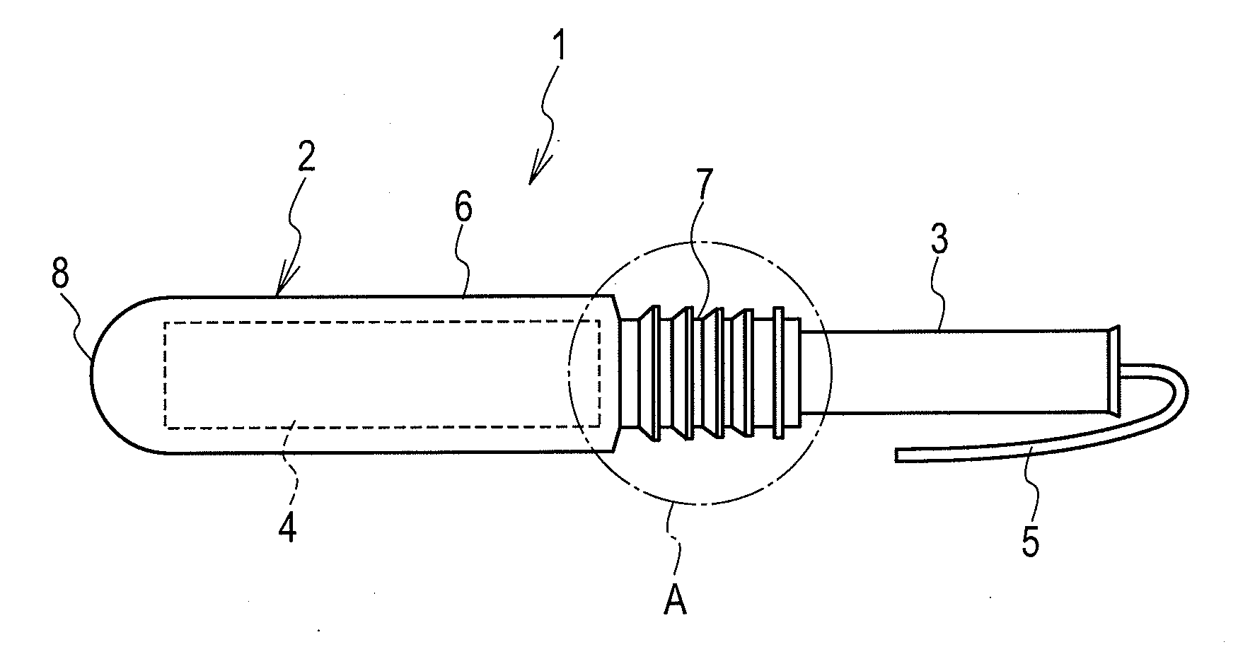
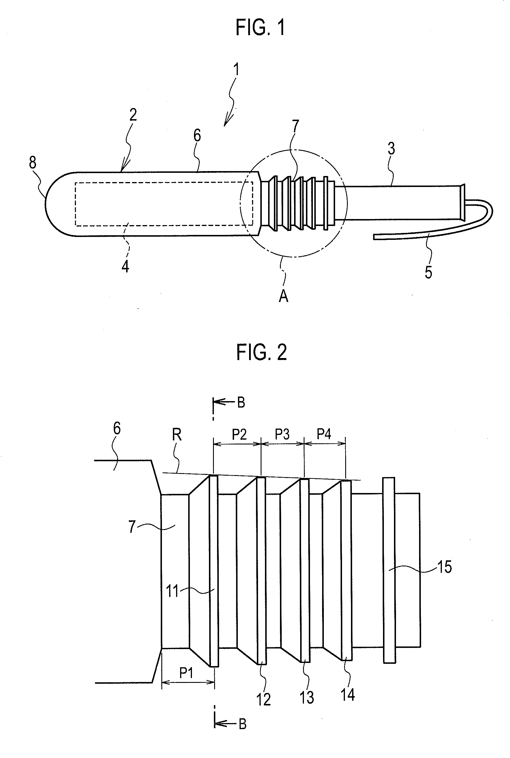
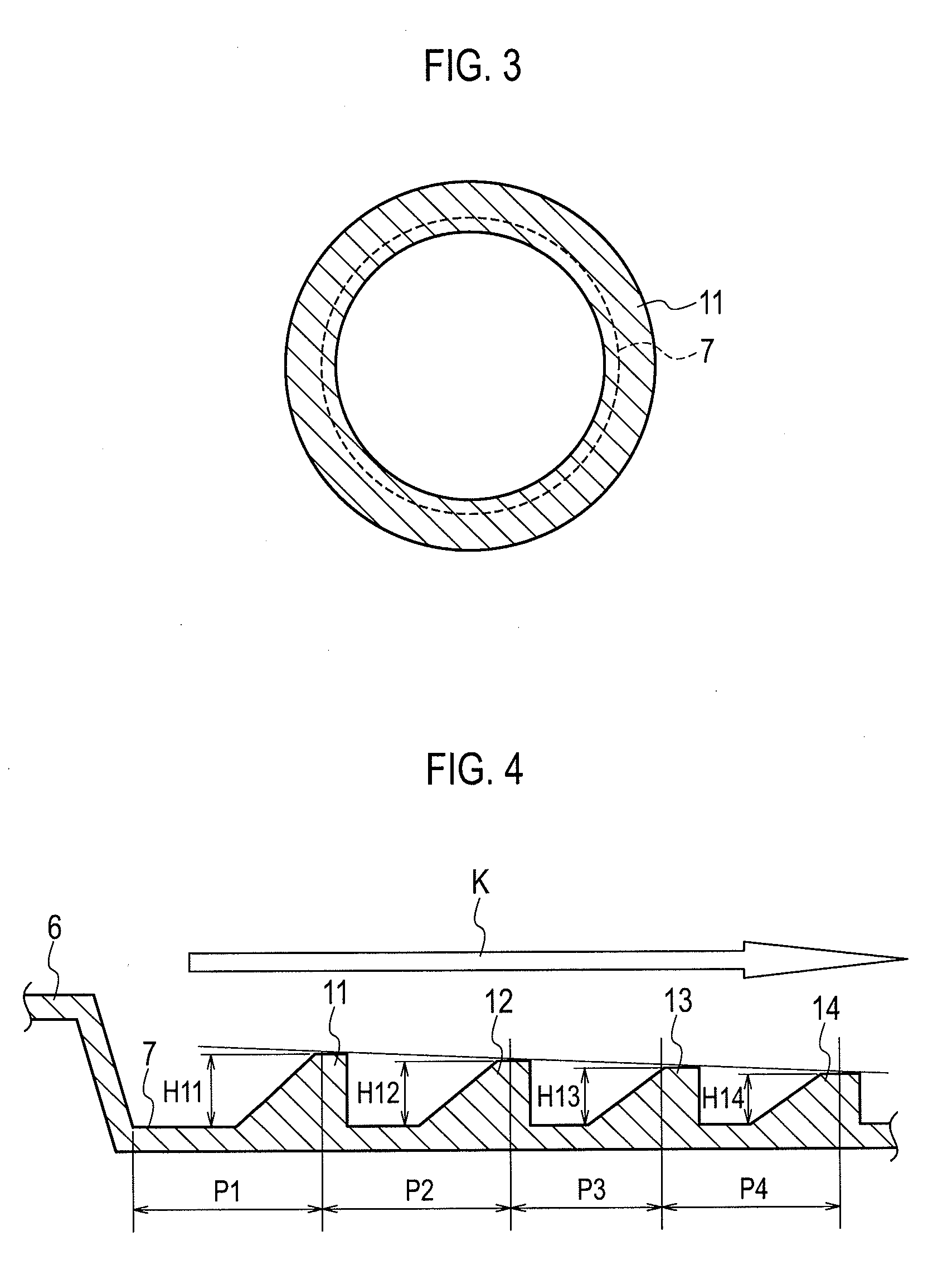
[0032]FIG. 1 is a front elevation illustrating an entire view of a tampon applicator according to the present invention. FIG. 2 is an front elevation illustrating an enlarged view of portion “A” in FIG. 1. FIG. 3 is a sectional view taken along line B-B in FIG. 2. FIG. 4 is a sectional view illustrating a geometrical relation of the annular projections. FIG. 5 is a sectional view illustrating a geometry of one annular projection. FIG. 6 is a graph illustrating a range of degree of inclination α of the inclined surfaces of the annular projections.

[0033]A tampon applicator 1 of this embodiment has an outer cylinder 2 and an inner cylinder 3. Entire portions of these outer cylinder 2 and the inner cylinder 3 are respectively composed of a polyolefin such as polyethylene, polypropylene or the like.

[0034]In the outer cylinder 2, an absorber 4 is housed. At the base end of the absorber 4, a drawstring 5 is connected. The drawstring 5 extends from the base end of the absorber 4, and passes...

second embodiment

[0051]FIG. 7 is a front elevation illustrating an entire view of a tampon applicator according to the present invention. FIG. 8 is a front elevation illustrating an enlarged view of portion “A1” in FIG. 7. FIG. 9 is a sectional view taken along line B1-B1 in FIG. 8. FIG. 10 is a sectional view illustrating the projection series taken at the same position with FIG. 9. FIG. 11 is a sectional view illustrating a geometrical relation of the projection series. FIG. 12 is a sectional view illustrating the geometry of one projection in the projection series. FIG. 13 is a graph illustrating a range of degree of inclinational of the inclined surface of the projection;

[0052]As illustrated in FIG. 8, there are a plurality of annular projection series 111, 112, 113 and 114 formed in a row on the outer circumference of the grip cylinder 107. The plurality of projections 111, 112, 113 and 114 in a row function as a non-slip, when brought into contact with the user's fingers. Reference numeral 115...


PUM


Abstract

An applicator for a tampon comprises an outer cylinder (2) containing an absorber (4) therein and provided with a petal-like components (8) for pushing out the absorber (4) on one side thereof and with a grip cylinder (7) on the other side thereof, and an inner tube (3) which is inserted into the grip cylinder (7) and can push out the absorber (4) to the outside from the petal-like components (8) by moving into the outer cylinder (2). A plurality of rows of annular protrusions (11, 12, 13, 14) are formed in the whole area of the grip cylinder (7) in the circumferential direction, such that the height from the outer circumferential surface of the grip cylinder (7) decreases gradually toward the side of the inner tube (3) being inserted into the grip cylinder (7).

Description

REFERENCE TO RELATED APPLICATIONS[0001]This application is a national stage application under 35 USC 371 of International Application No. PCT / JP2009 / 056074, filed Mar. 26, 2009, which claims the priority of Japanese Application Nos. 2008-018950, filed Mar. 26, 2008, and 2008-081964, filed Mar. 26, 2008, the contents of which prior applications are incorporated herein by reference.FIELD OF THE INVENTION[0002]The present invention relates to a tampon applicator housing an absorber and ejecting the absorber when it is used.BACKGROUND OF THE INVENTION[0003]A tampon applicator has an outer cylinder housing an absorber, and an inner cylinder ejecting the absorber housed in the outer cylinder. The outer cylinder and the inner cylinder are formed by injection molding of resin. The inner cylinder is handled so as to move into the outer cylinder. This handling acts to eject the absorber out from the outer cylinder. An ejection opening formed at the end of the outer cylinder is provided with p...

Claims


Application Information

Patent Timeline
Patent Type & Authority Applications(United States)
IPC IPC(8): A61F13/32
CPCA61F13/266
Inventor WATANABE, HITOSHIKONDO, HIDEKI
Owner UNI CHARM CORP
Why Eureka
Try Eureka