
Power Monitoring and Analysis System for Identifying and Tracking Individual Electrical Devices

a technology of power monitoring and analysis system, applied in the field of energy monitoring system, can solve the problems of additional power sensors, separate complex power monitors used for each electrical device, and the total power used by the device during a period of tim

Inactive Publication Date: 2011-06-16
VERLITICS
View PDF9 Cites 69 Cited by
  • Summary
  • Abstract
  • Description
  • Claims
  • Application Information

AI Technical Summary

Benefits of technology

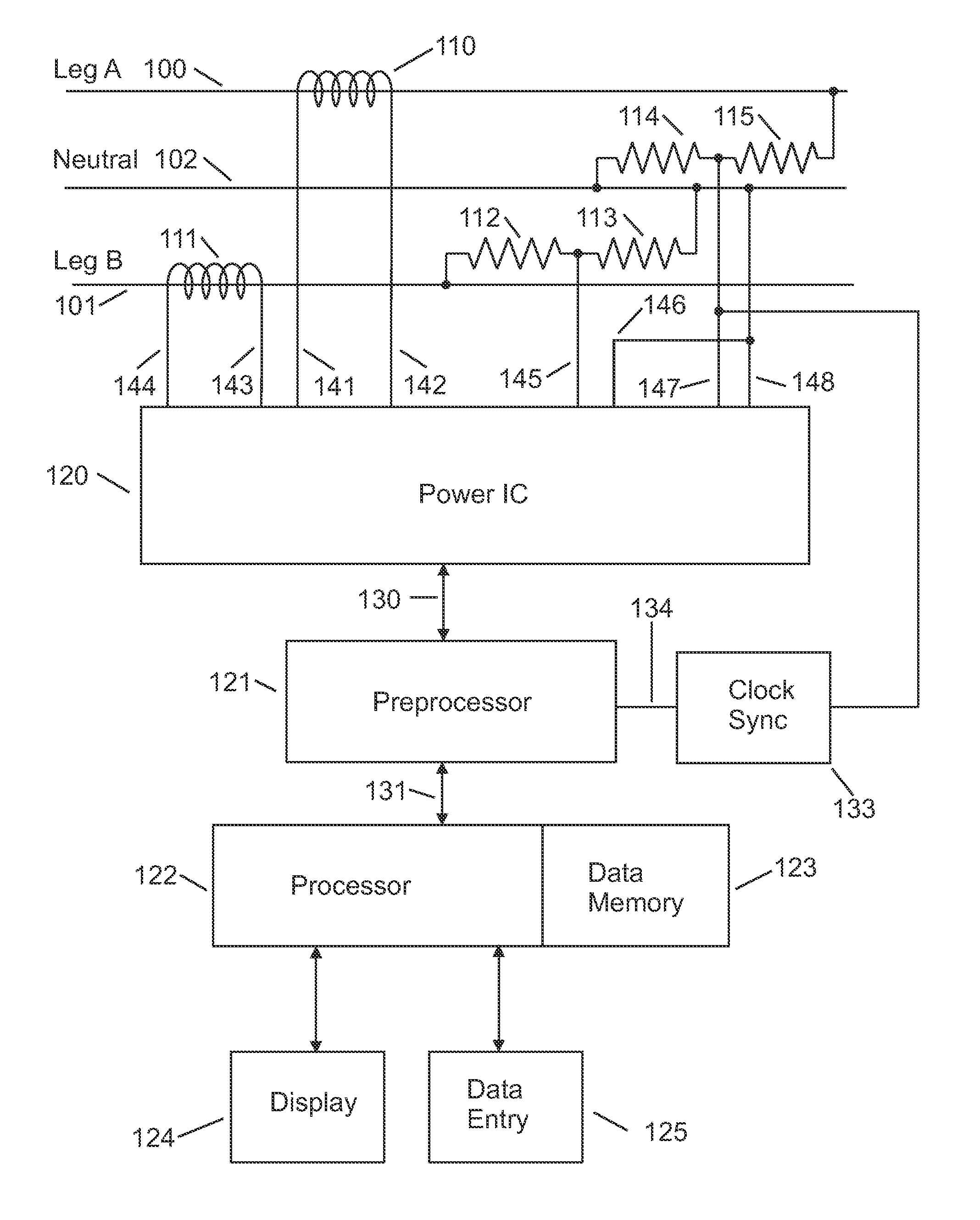
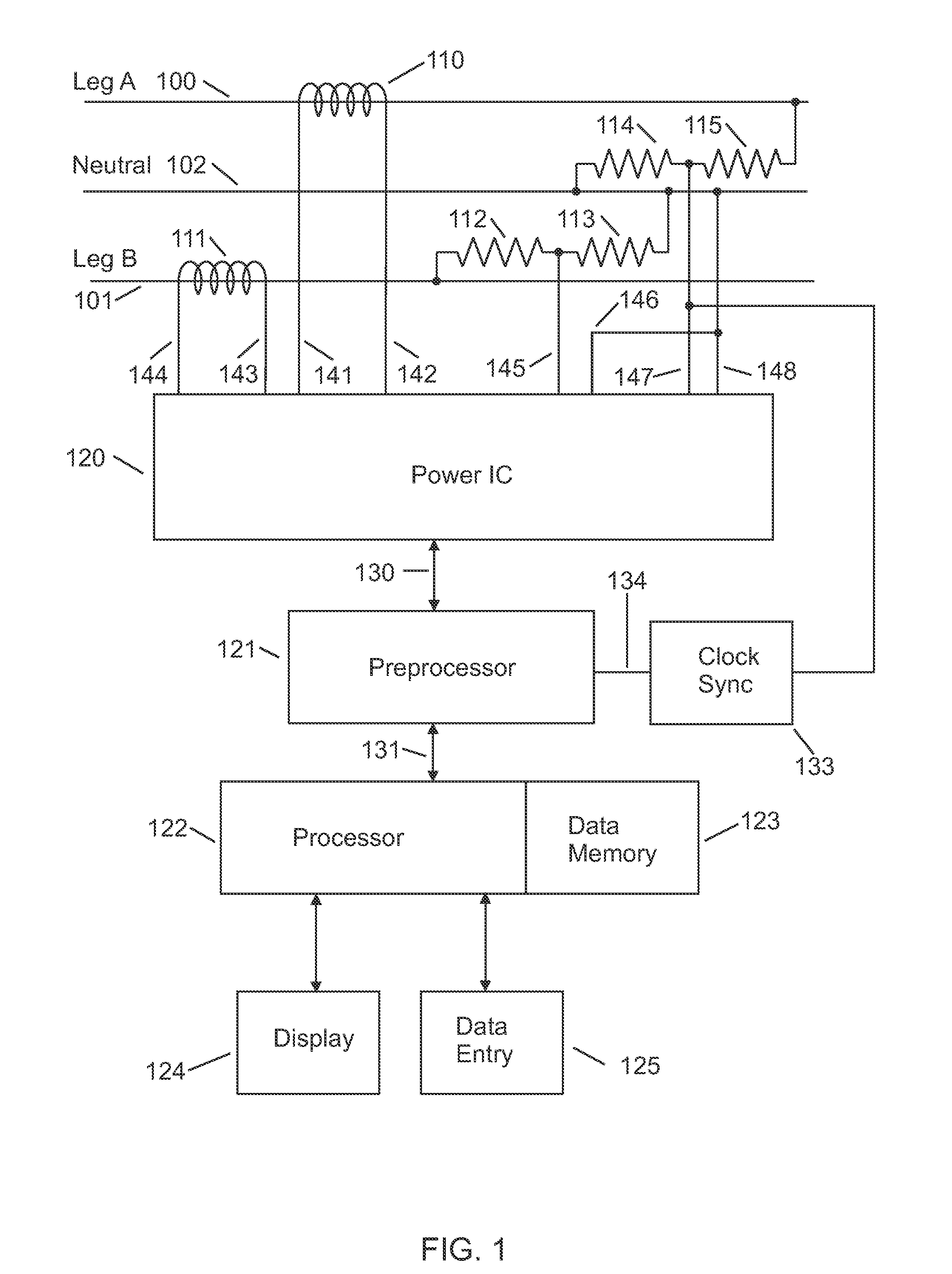
[0023]The invention is a method for measuring and processing a plurality of electrical parameters of a common alternating current (AC) service that supplies multiple different electrical devices such that the power use rate and total power used by each of multiple devices is determined. Sensors provide high resolution signals corresponding to the current and voltage of the AC power supplied to the service panel typical of those used in residential construction. Analog-to-digital conversion and processing circuits determine multiple electrical parameters with high resolution at a sampling rate sufficient to determine the electrical parameters for approximately each AC cycle. The electrical parameters are stored as a large data set in a memory with sufficient capacity to store several months of electrical parameters representing each AC cycle. The data set is processed to extract complete on-off cycles of the devices. The on-off cycles are represented by instance structures. The characteristics of the instance structures are used to determine device structures. Each device structure characterizes one of the multiple devices. The contributions associated with the extracted instance structures are subtracted from the data set, making is possible to extract additional instance structures from the residual information in the data set. Information from the device structures are used to help extract instances structures that are partially obscured by overlapping instance structures. The newly extracted instances structures are subtracted from the data set and processing continues until no more instance structures can be extracted. Information from the extracted instance structures and device structures are further grouped and processed to provide useful information reports to a consumer. As the electrical parameters are determined and added to the data set, they can be incrementally processed so that near real time information can be provided to the consumer. The cost of operating each device and other information enables the consumer to make informed decision regarding energy use and conservation.

Problems solved by technology

The device also accumulates the total power used during a period of time and its cost.
The disadvantage of this approach is that a separate complex power monitor is used for each electrical device.
The disadvantage of this approach is an additional power sensor and a method of reporting its measurements are needed for each device monitored.
However, Hart et al. has many limitations that make it impractical for use in most modern residential homes.
Many devices use variable power while they are on, so the turn on and turn off steps do not match; therefore they can not be accurately tracked.
This introduces large uncertainty in step measurements, especially at the measurement rate of one sample per second preferred by Hart et al.
A slower rate can be used, but this leads to more frequent errors by the device.
For example HVAC fans may take a minute or more to reach full speed, so the rate of change is very small.
Such a step is difficult to detect given the disclosed behavior of the “steady state detector 22”.
Hart et al. discloses a technique that works only for very limited circumstances, and does not provide a practical method of tracking multiple electrical devices in a typical residential home.
“Searching for complete transients is an undesirable approach because it limits the tolerable rate of event generation.
However, Leeb et al. does not disclose how to make a practical power monitor for residential home because it provides only modest improvement in the ability to deal with overlapping turn on transients and provides no improvement in associating turn off transients with devices that are on.
Therefore it does not enable tracking individual electrical devices in a typical residential home.

Method used


Image

  • Power Monitoring and Analysis System for Identifying and Tracking Individual Electrical Devices
  • Power Monitoring and Analysis System for Identifying and Tracking Individual Electrical Devices
  • Power Monitoring and Analysis System for Identifying and Tracking Individual Electrical Devices

Examples


Embodiment Construction

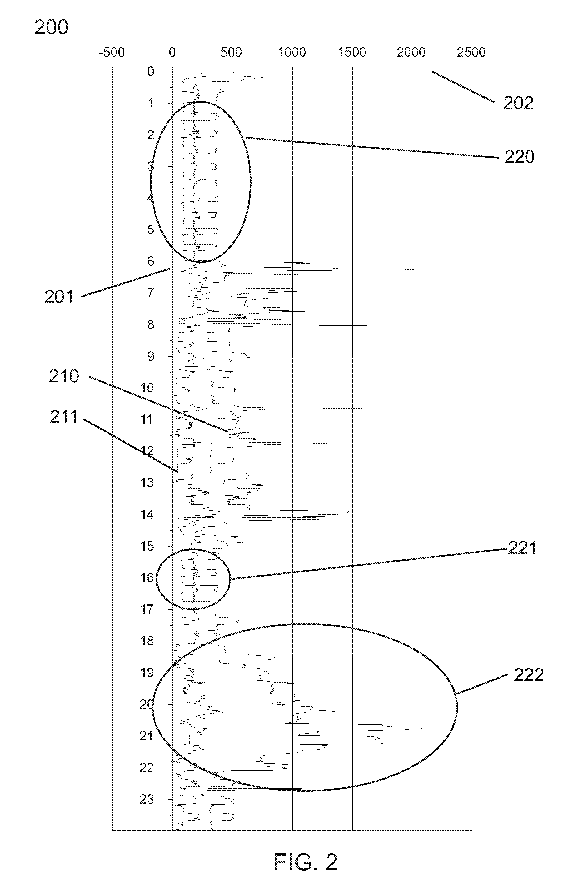
[0043]A typical household has dozens of different electrical devices that consume electrical power. Households typically have single examples of appliances such as HVAC equipment, washer, dryer, refrigerator, stove, microwave, toaster, coffeemaker, etc. Each of these devices has specific electrical behaviors during a complete on-off cycle. It is very unlikely that the combination of these behaviors is identical for different devices. Even though the average continuous real power may be the nearly identical for some devices, differences in the electrical parameters during a complete on-off cycle will generally be sufficiently different to enable unique identification.

[0044]Multiple instances of the same device served by the same supply generally can not be uniquely identified. For example, all 60-watt incandescent light bulbs will be recognized as the same device. However, multiple instances of 60-watt lights can be tracked by keeping count as they are turned on and off. If two 60-wa...


PUM


Abstract

The invention is a method for measuring and processing a plurality of electrical parameters of a common alternating current (AC) service that supplies multiple different electrical devices such that the power use rate and total power used by each of multiple devices is determined. Sensors provide high resolution signals corresponding to the current and voltage of the AC power supplied to the service panel typical of those used in residential construction. Analog-to-digital conversion and processing circuits determine multiple electrical parameters with high resolution at a sampling rate sufficient to determine the electrical parameters for approximately each AC cycle. The electrical parameters are stored as a large data set in a memory with sufficient capacity to store several months of electrical parameters representing each AC cycle. The data set is processed to extract complete on-off cycles of the devices. The on-off cycles are represented by instance structures. The characteristics of the instance structures are used to determine device structures. Each device structure characterizes one of the multiple devices. The contributions associated with the extracted instance structures are subtracted from the data set, making is possible to extract additional instance structures from the residual information in the data set. Information from the device structures are used to help extract instances structures that are partially obscured by overlapping instance structures. The newly extracted instances structures are subtracted from the data set and processing continues until no more instance structures can be extracted. Information from the extracted instance structures and device structures are further grouped and processed to provide useful information reports to a consumer. As the electrical parameters are determined and added to the data set, they can be incrementally processed so that near real time information can be provided to the consumer. The cost of operating each device and other information enables the consumer to make informed decision regarding energy use and conservation.

Description

BACKGROUND OF THE INVENTION[0001]1. Technical Field of the Invention[0002]This invention relates generally to energy monitoring systems and more specifically to electrical power monitors as used in residential energy management systems.[0003]2. Background Art[0004]There is a broad growing interest in energy conservation. Reducing residential electrical consumption is a priority for national, state, and local governments, for utilities, and for consumers. It is especially important to reduce electrical consumption during peak load periods, typically in the afternoon on hot days. It is generally accepted that consumers are more likely to change their behavior if they are made aware of where, when, and how they use electricity in their household and how much it costs. A power monitoring system provides this information.[0005]The simplest monitor displays the present rate of power use. Its function is similar to the power meter used by the utility company for billing, but it displays th...

Claims


Application Information

Patent Timeline
Patent Type & Authority Applications(United States)
IPC IPC(8): G06F19/00G01R21/00
CPCG01D4/002H02J13/0086Y02B70/3266Y02B90/241Y02E60/74Y04S20/32Y04S20/38Y04S10/30Y04S20/242H02J13/00002H02J2310/70H02J13/00028Y02B70/30Y02E60/00G01D2204/24H02J13/00016H02J13/00001Y04S10/40Y04S40/124Y02B90/20Y04S20/30
Inventor ALLES, HAROLD GENE
Owner VERLITICS
Learn More