

IDeal Garden Marker
a technology of garden markers and markers, applied in the field of ideal garden markers, can solve problems such as friction or interferen
- Summary
- Abstract
- Description
- Claims
- Application Information
AI Technical Summary
Benefits of technology
Problems solved by technology
Method used
Image

Examples
Embodiment Construction
While this invention may be embodied in many different forms, there are shown in the drawings and described in detail herein specific preferred embodiments of the invention. The present disclosure is an exemplification of the principles of the invention and is not intended to limit the invention to the particular embodiments illustrated.
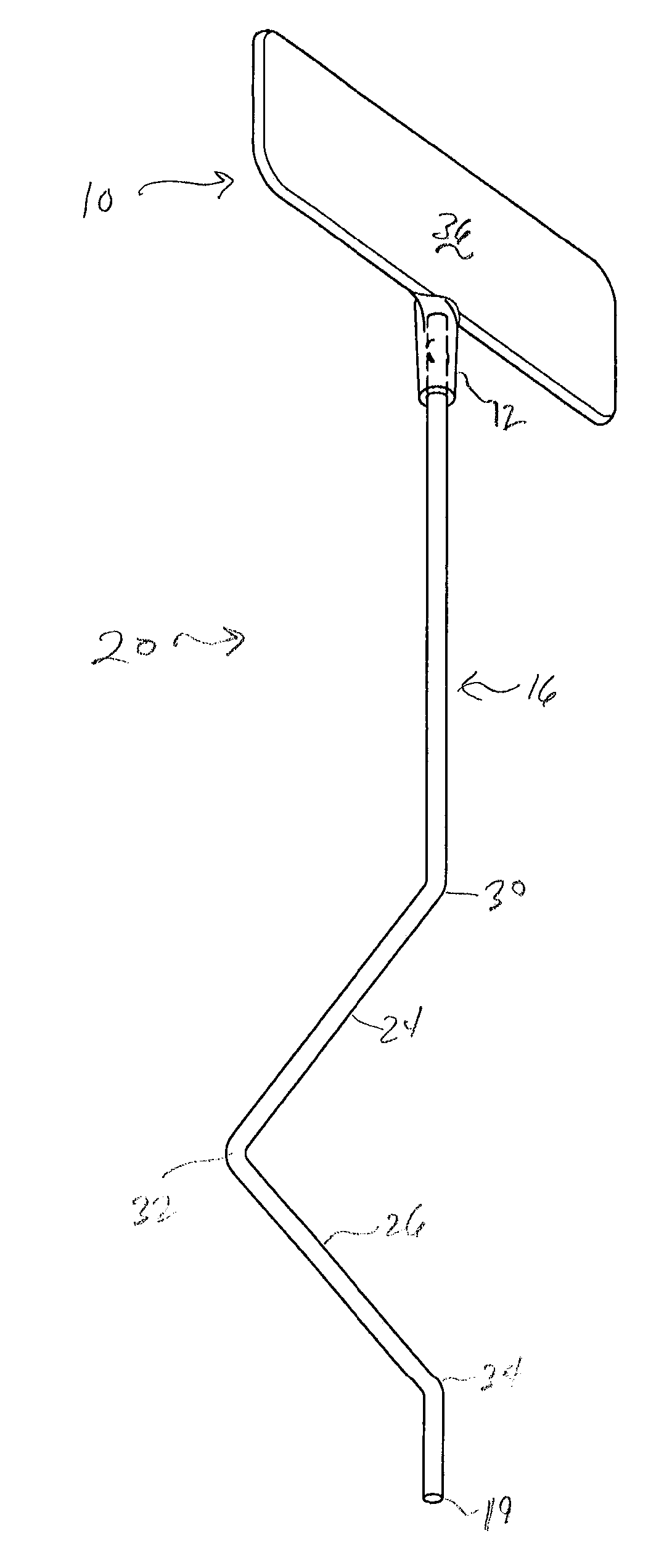
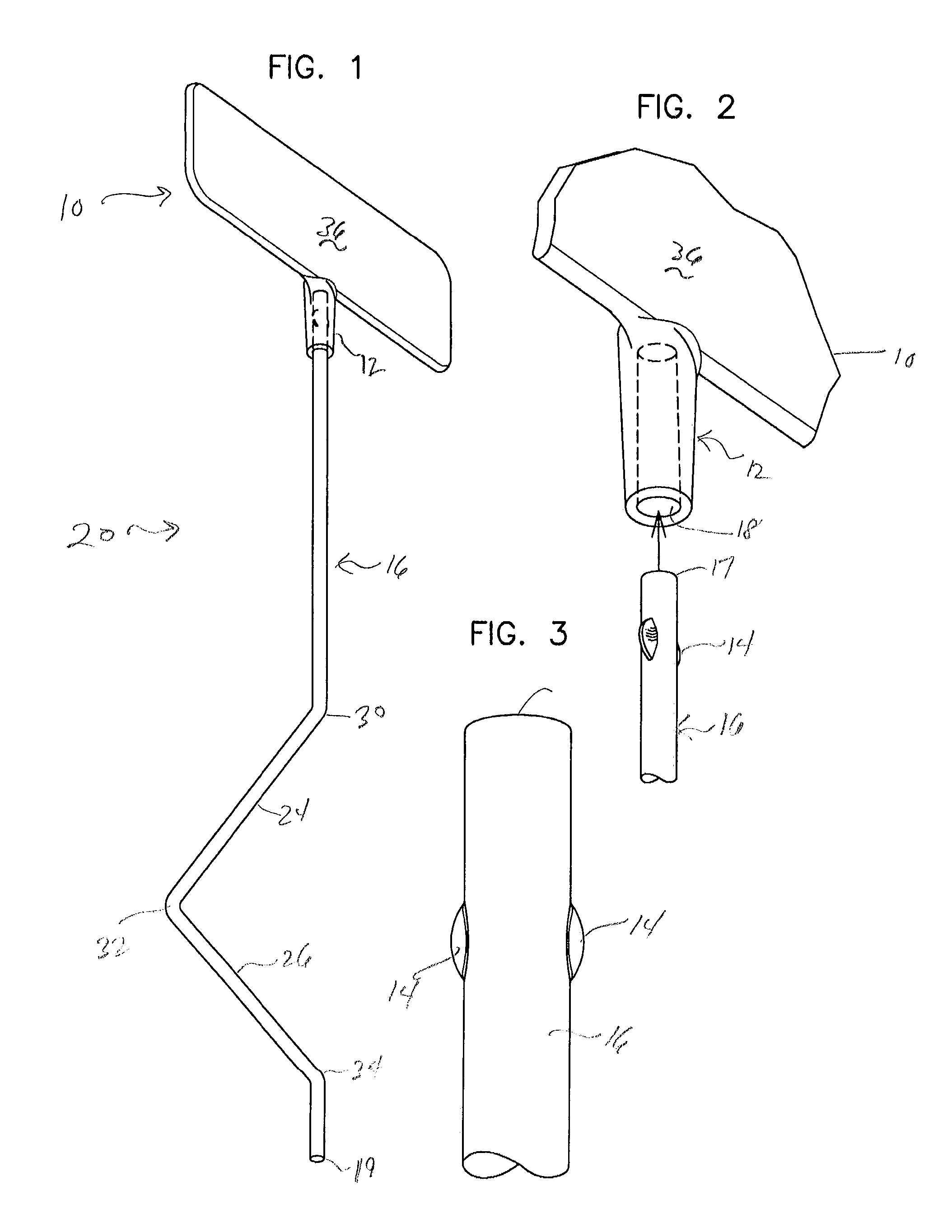
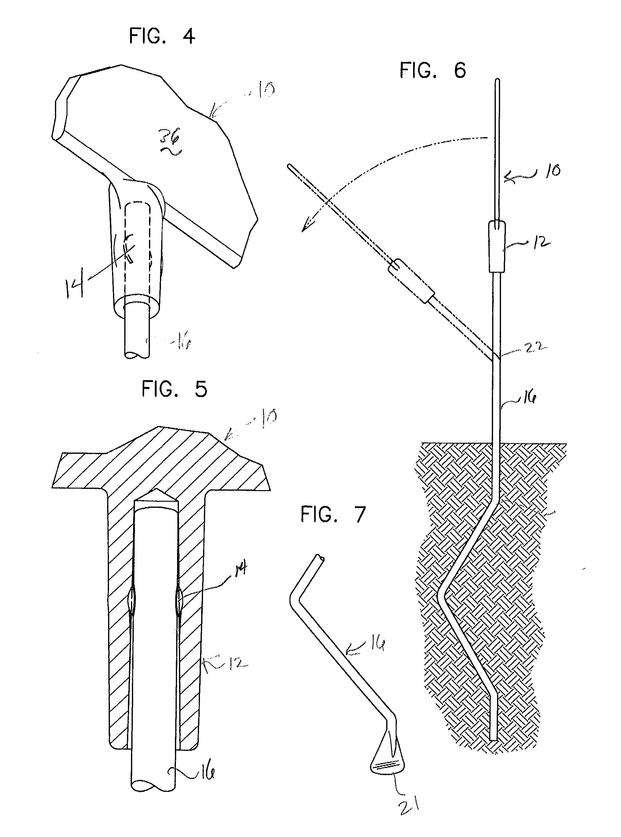
There are two separate parts to the innovative garden marker designs. One part is a stake made of metal or plastic. The second part is a plastic nameplate that is designed in a new, innovative way. As gardeners would prefer to have two sides of a marker to add adhesive backed labels or written text to, or additional nameplates such as engraved nameplates, attaching the metal garden stake from a side, and preferably the bottom of the name plate is important. This new design makes that easy and functional.
The nameplates are designed so that much of it has a surface on one and preferably two sides that is significantly flat in the area the information w...
PUM
 Abstract
Description
Claims
Application Information