Power extraction system

Inactive Publication Date: 2011-06-23
GENERAL ELECTRIC CO
View PDF21 Cites 4 Cited by
  • Summary
  • Abstract
  • Description
  • Claims
  • Application Information

AI Technical Summary

Benefits of technology

[0007]Accordingly, it would be desirable to have a gas turbine engine having a power extraction system

Problems solved by technology

This typically requires that the maximum operating airflow in the core be limited below its full design corrected airflow capacity due to mechanical limitations of the maximum physical core speed and / or the maximum compressor discharge temperature capability of the core.
In some cases, such high power loads may require major compromises in the propulsion engine design in order to support them while maintaining engine operability.
Some aircraft and mission applications require very rapid response to large changes in the external load demand, which are difficult to accommodate with conventional power offtake configurations due to the inertias of the engine rotors and the spool speed changes needed to provide the additional power.
Therefore, high power extraction for external use from the low-pressure spool or the high-pressure spool may not be desirable in some cases.

Method used


Image

  • Power extraction system
  • Power extraction system
  • Power extraction system

Examples


Embodiment Construction

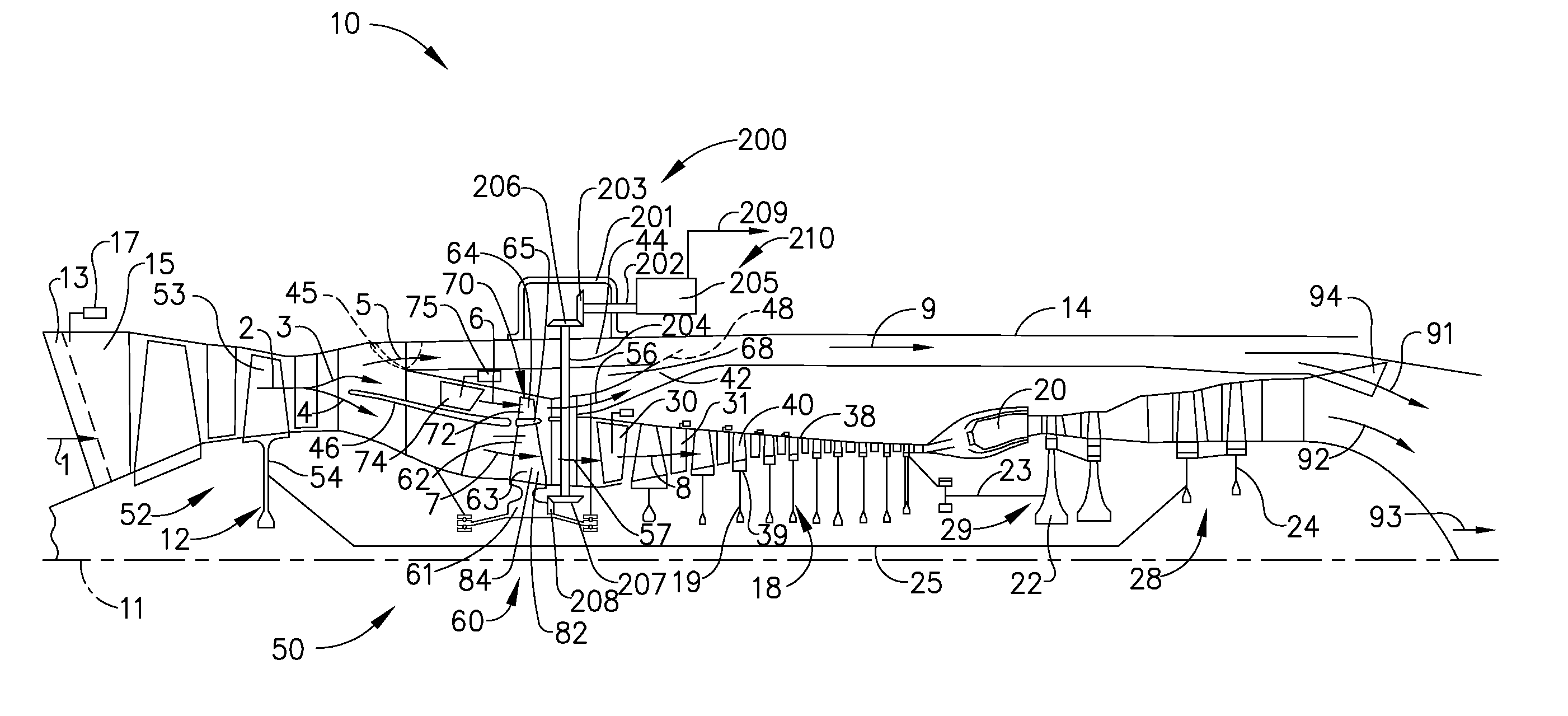
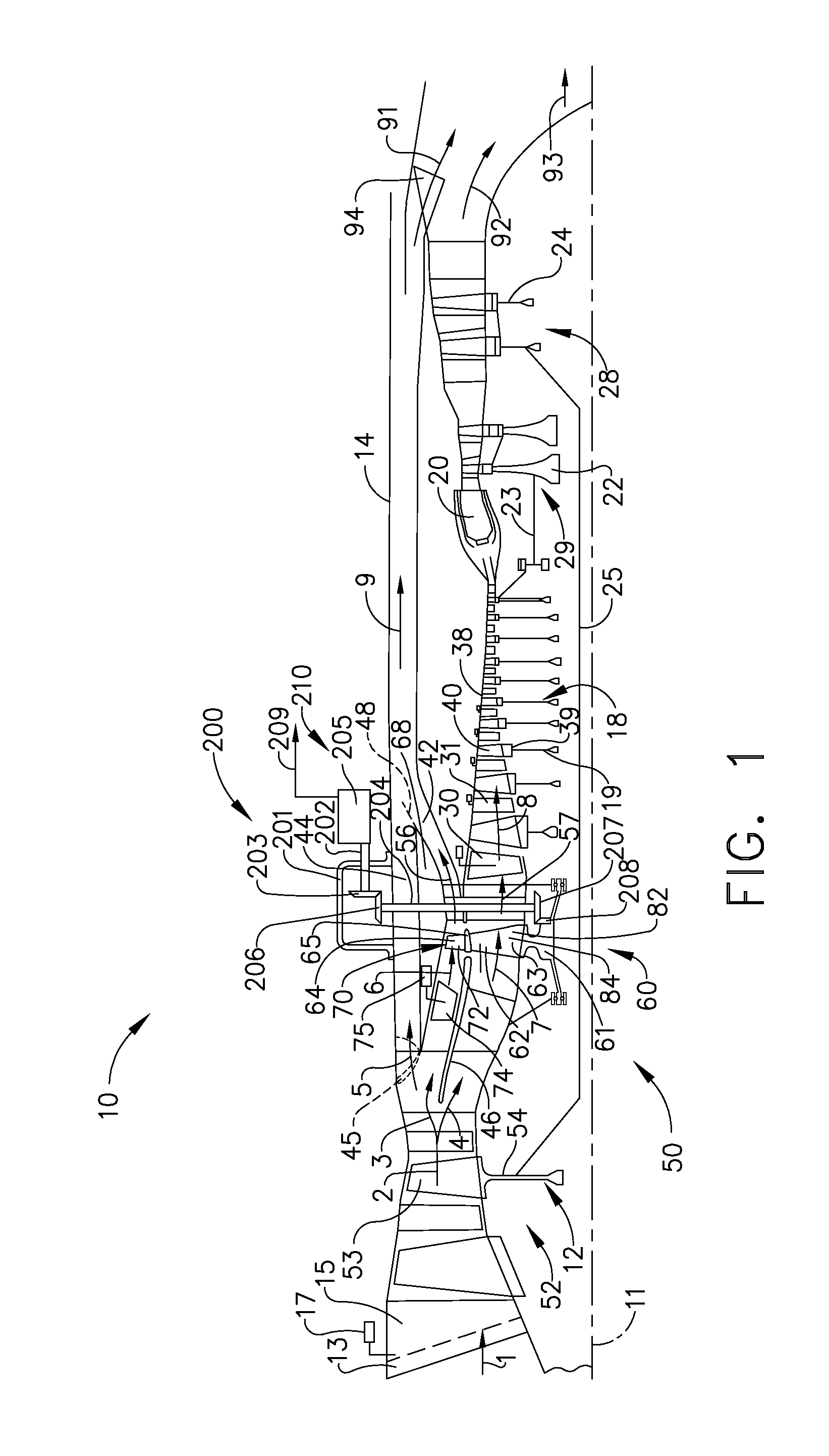
[0016]Referring to the drawings wherein identical reference numerals denote the same elements throughout the various views, FIG. 1 shows an exemplary turbofan gas turbine engine 10 incorporating an exemplary embodiment of the present invention. The exemplary gas turbine engine 10 comprises an engine centerline axis 11, a fan 12 which receives an inflow of ambient air 1, an optional booster or low-pressure compressor (LPC) (not shown in FIG. 1), a high-pressure compressor (HPC) 18, a combustor 20 which mixes fuel with the air pressurized by the HPC 18 for generating combustion gases which flow downstream through a high-pressure turbine (HPT) 22, and a low-pressure turbine (LPT) 24 from which the combustion gases are discharged from the engine 10. The HPT 22 is coupled to the HPC 18 using a HPT shaft 23 to substantially form a high-pressure rotor 29. A low-pressure shaft 25 joins the LPT 24 to the fan 12 (and the optional booster if present) to substantially form a low-pressure rotor ...


PUM


Abstract

A power extraction system is disclosed having a forward fan stage configured to pressurize an airflow, an aft fan stage having a tip-fan configured to pressurize a first portion of a pressurized air flow from the forward fan stage wherein the aft fan stage is driven by a second portion of the pressurized airflow, and a power drive system adapted to supply power from the aft fan stage.

Description

CROSS-REFERENCE TO RELATED APPLICATIONS[0001]This application claims priority to U.S. Provisional Application Ser. No. 61 / 288,369, filed Dec. 21, 2009, which is herein incorporated by reference in its entirety.BACKGROUND OF THE INVENTION[0002]This invention relates generally to gas turbine engines, and, more specifically, to a gas turbine engine with a power extraction system having an intermediate pressure fan stage having a blade driven by a pressurized airflow.[0003]In a turbofan aircraft gas turbine engine, air is pressurized in a fan module, an optional booster module and a compression module during operation. A portion of the air passing through the fan module is passed into a by-pass stream and used for generating a portion of the thrust needed for propelling an aircraft in flight. The air channeled through the optional booster module and compression module is mixed with fuel in a combustor and ignited, generating hot combustion gases which flow through turbine stages that ex...

Claims


Application Information

Patent Timeline
IPC IPC(8): F02K9/00
CPCF02C7/32F02K3/077F02K3/065F02K3/06
Inventor BAUGHMAN, JOHN LEWIS
Owner GENERAL ELECTRIC CO
Why Eureka
Try Eureka