
Bioretention System With High Internal High Flow Bypass

a bioretention system and high-flow technology, applied in water cleaning, multi-stage water/sewage treatment, separation processes, etc., can solve the problems of increasing the maintenance frequency of typical bioretention systems, reducing efficiency, and adding design, manufacturing, installation and maintenance costs

Active Publication Date: 2011-06-23
OLDCASTLE PRECAST
View PDF47 Cites 37 Cited by
  • Summary
  • Abstract
  • Description
  • Claims
  • Application Information

AI Technical Summary

Benefits of technology

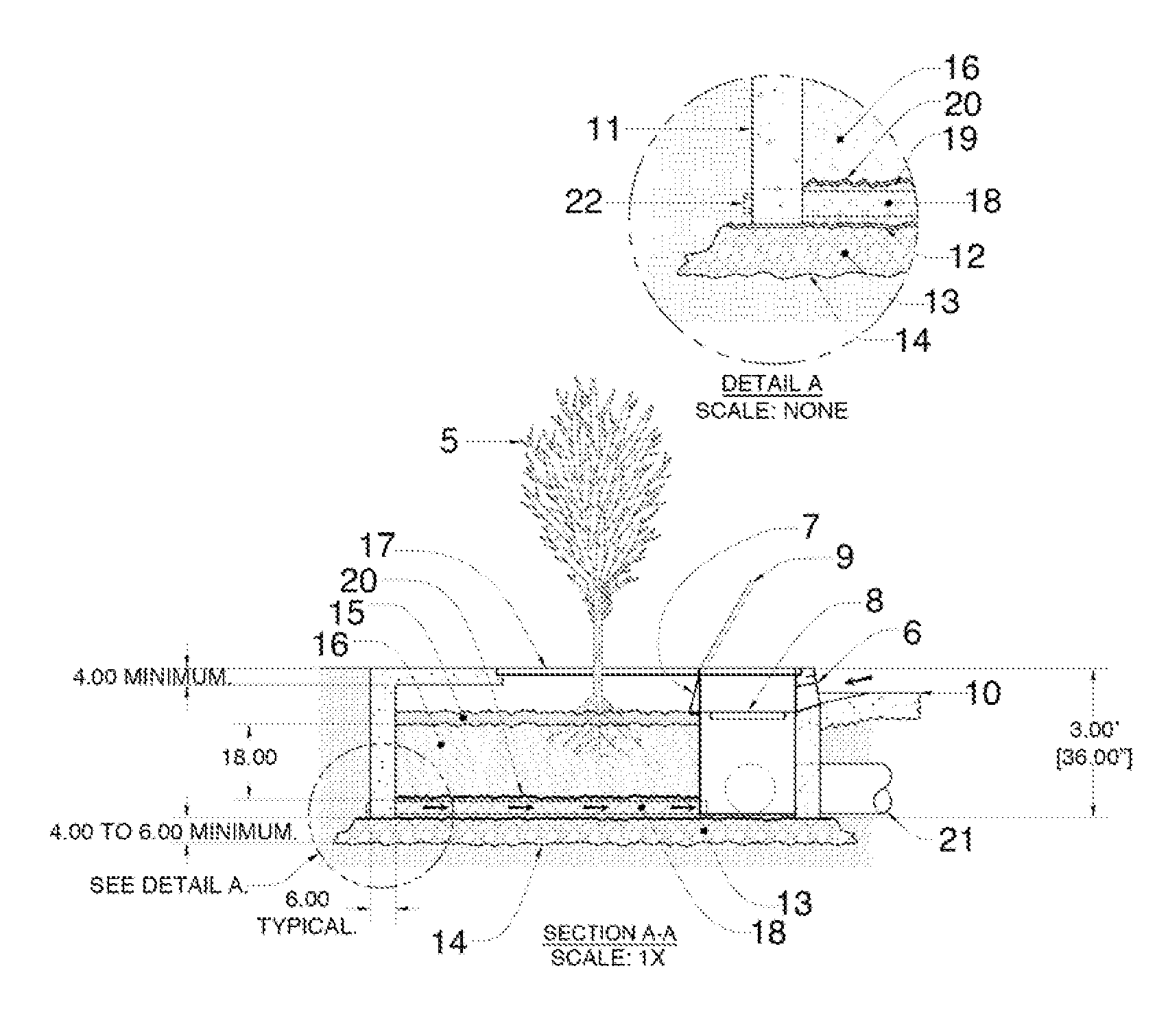
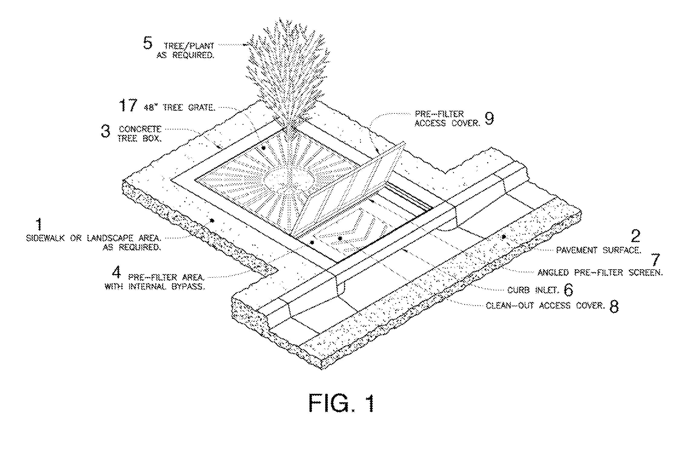
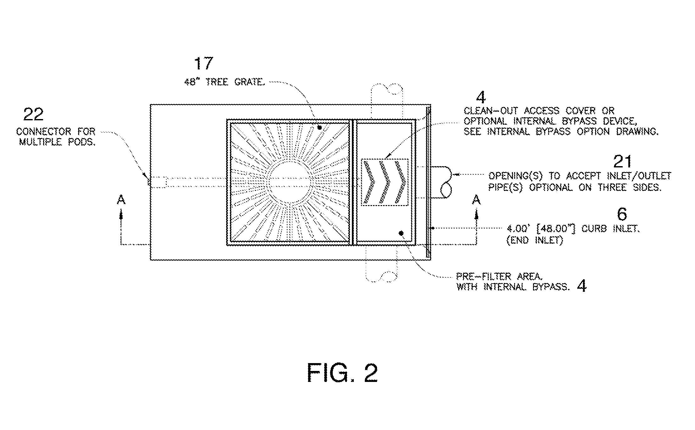
[0020]Another feature of the bioretention system is that it may be assembled in various configurations and used in conjunction with existing storm water storage systems. These include connections to a pipe, chamber, or modular water storage system to address site hydromodification and water quality on a developed site. The pre-filter and biofiltration chambers can be disposed in different configurations relative to a curb or drain inlet to accommodate different surface structures and site requirements. Treated flows may be collected, stored, or infiltrated to help meet different design criteria for the site.
[0021]In the below description, numerous specific details are provided, such as the identification of various system components, to provide an understanding of embodiments of the invention. Numerous other variations and embodiments can be discerned from the above-detailed description of the intentions and illustrations thereof. One skilled in the art will recognize, however, that embodiments of the invention can be practiced without one or more of the specific details, or with other methods, components, materials, etc. In still other instances, well-known structures, materials, or operations are not shown or described in detail to avoid obscuring aspects of various embodiments of the invention. All such variations are encompassed within the scope and spirit of the present invention.

Problems solved by technology

As a result, storm water runoff can accumulate pollutants such as oil and debris, which then flows into a sewer system or other receiving water bodies.
However, because the high flow bypass is an external structure—externally added to the tree box or other bioretention system components—its incorporation with tree box filters requires additional space (to accommodate the external bypass structure), as well as additional design, manufacturing, installation, and maintenance costs.
The entrance of gross pollutants, such as trash, debris, floatables, and coarse sediments, are known to “clog” the system and thus reduce the efficiency.
It also increases the maintenance frequency of typical bioretention systems.

Method used


Image

  • Bioretention System With High Internal High Flow Bypass
  • Bioretention System With High Internal High Flow Bypass
  • Bioretention System With High Internal High Flow Bypass

Examples


Embodiment Construction

[0036]As used herein, the terms “comprises,”“comprising,”“includes,”“including,”“has,”“having” or any other variation thereof, are intended to cover a non-exclusive inclusion. For example, a process, method, article, or apparatus that comprises a list of elements is not necessarily limited to only those elements but may include other elements not expressly listed or inherent to such process, method, article, or apparatus. Further, unless expressly stated to the contrary, “or” refers to an inclusive or and not to an exclusive or. For example, a condition A or B is satisfied by any one of the following: A is true (or present) and B is false (or not present), A is false (or not present) and B is true (or present), and both A and B are true (or present).

[0037]Also, use of the “a” or “an” are employed to describe elements and components of the invention. This is done merely for convenience and to give a general sense of the invention. This description should be read to include one or at ...


PUM

PropertyMeasurementUnit
elevationaaaaaaaaaa
areaaaaaaaaaaa
maintenance frequencyaaaaaaaaaa

Abstract

The invention provides a bioretention system comprising one or more chambers and a high flow bypass system with top and bottom weirs for water filtration and storm water flow management. The invention also provides methods that are useful for managing storm water flow and inhibiting the flow of pollutants, debris, and other contaminants into drainage systems.

Description

CROSS-REFERENCE TO RELATED APPLICATION[0001]This application claims the benefit of U.S. Provisional Application No. 61 / 289,376, filed Dec. 22, 2009.FIELD OF THE INVENTION[0002]The present invention relates to storm water management systems that are useful for the control of storm water runoff and the removal of pollutants, debris, and other contaminants from storm water runoff; and more specifically, to bioretention systems that are useful for managing storm water flow and inhibiting the flow of pollutants, debris, and other contaminants into drainage systems.BACKGROUND OF THE INVENTION[0003]Many federal and state regulatory schemes require controlling storm water run-off and water quality, such as levels of pollutants on new developments of land. Before land development, an area will likely have included a variety of natural land features, such as sand dunes, grassy hills and wetlands. The natural land features absorb rainwater and infiltrate storm water runoff into the soil to rep...

Claims


Application Information

Patent Timeline
Patent Type & Authority Applications(United States)
IPC IPC(8): C02F3/00C02F1/00
CPCC02F3/327C02F2103/001E03F5/16E03F5/0404E03F5/14C02F2303/24Y02W10/10
Inventor ALLARD, DOUGLAS
Owner OLDCASTLE PRECAST
Learn More